© by WilTec Wildanger Technik GmbH Item 65057 Page 13
http://www.wiltec.de 09 2024-1
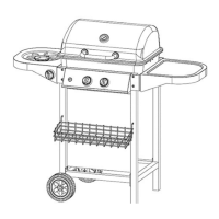
Step 5
Attach the burner housing (2) to the left frame combination (11) and right frame combination (12) using
the M5×12 screws (A).
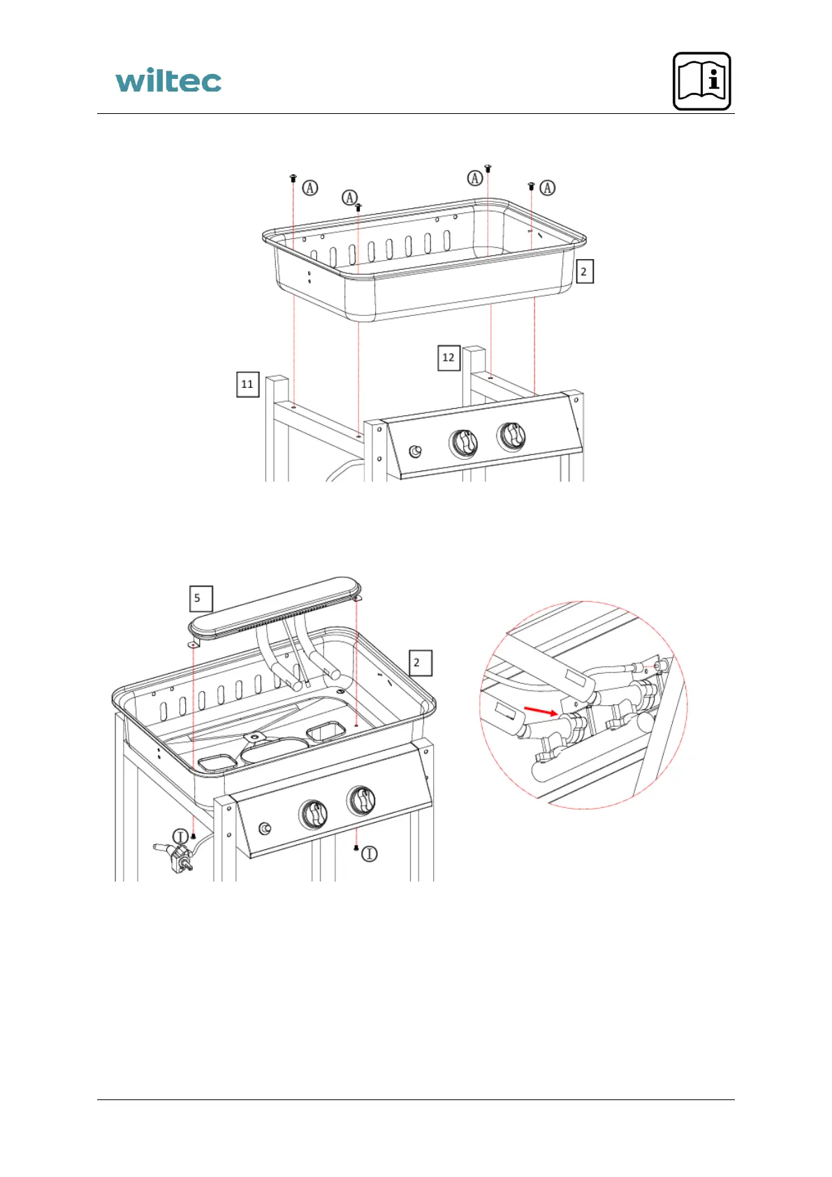
Step 6
1. Insert the burner (5) through the opening in the burner housing (2).
2. Align the valves on the control panel (13) with the venturi tubes on the burner (5).
3. Ensure that all valve tips fit fully into the venturi tubes and are well aligned.
4. Secure the burner (5) to the burner housing (2) using M3×10 screws (I).
5. Insert the burner electrode into the valve on the control panel (13).
Caution! Insert the burner (5) so that the nozzles of the control knobs extend into the burner connection
tubes. The ends of the tubes should loosely sit over the nozzles. This air gap is desired.
 Loading...