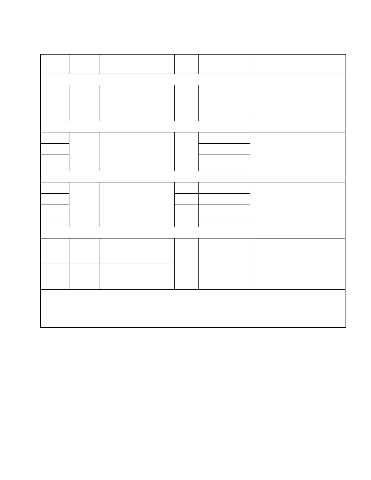
Models
Directivity
(dB)
Accuracy➀
Input Z
(ohms)
Test Port
Connector
Physical
58 Series Comparison SWR Bridge
,
2 to 18 GHz
58A50 35
2–3 GHz:
0.018 ±0.32ρ
2
➁ ➂
3–4 GHz:
0.018 ±0.2ρ
2
4–18 GHz:
0.018 ±0.13ρ
2
50 GPC–7
Dimensions:
6.7 x 5.1 x 2.2 cm
(2
5
⁄
8
x 2 x
7
⁄
8
in.) plus connectors
Weight:
340 g (12 Oz)
60 Series SWR Bridges, 5 MHz to 2 GHz
60A50
40➃
0.01 ±0.09ρ
2
50
GPC–7
Dimensions:
6.7 x 5.1 x 2.54 cm
(2
5
⁄
8
x 2 x 1 in.) plus connectors
Weight:
340 g (12 oz)
60N50 Type N Male
60NF50 Type N Female
62 Series SWR Bridges, 10 MHz to 1GHz
62N75➄
40
0.01 ±0.12ρ
2
75 Type N Male
Dimensions:
6.7 x 5.1 x 2.54 cm
(2
5
⁄
8
x 2 x 1 in.) plus connectors
Weight:
170 g (6 Oz)
62NF75 75 Type N Female
62B75 75 BNC Male
62BF75 75 BNC Female
87 Series SWR Bridges,
2 to 18 GHz
87A50
35
2–3 GHz:
0.018 ±0.32ρ
2
3–4 GHz:
0.018 ±0.2ρ
2
4–18 GHz:
0.018 ±0.13ρ
2
50 GPC–7
Dimensions:
7.3 x 5.1 x 2.86 cm
(2
5
⁄
8
x 2 x 1
1
⁄
8
in.) plus connectors
Weight:
340 g (12 Oz)
87A50-1
38
2–3 GHz:
0.013 ±0.32ρ
2
3–4 GHz:
0.013 ±0.2ρ
2
4–18 GHz:
0.013 ±0.13ρ
2
All Models
Insertion Loss (from input to test port): 6.5 dB nominal
Maximum Power Input: 0.5 watts (+27 dBm)
Input Connector: Type N Female, stainless steel, except 67B and 67F Series that have BNC Female
➀ Where ρ is the reflection coefficient being measured. Accuracy includes the effects of test port reflections and directivity.
➁ When used with 28A50-1 Precision Termination. The effective directivity of the bridge can be increased to 60 dB by using the Ripple
Extraction return loss measurement technique with the 18A50 Air Line and 29A50-20 Offset Termination.
➂ See paragraph 4 for explanation of accuracy and other terms.
➃ 46 dB directivity available as Option 1. Option 1 accuracy: 0.005 ±0.09ρ
2
.
➄ 75Ω Type N Female connectors will withstand occasional mating with 50Ω connectors without damage.
Table 2. SWR Bridge Performance Specifications
SWR OMM 3
 Loading...