x
DE
Für Fenster mit Wetterschenkel (z. B. Holzfenster) messen Sie die Blendrahmenstärke X1 (oben) und X2 (unten) des Fensterstocks mittels Maßband. Der Blendrahmen ist der
äußerste Schenkel des Stocks bei geöffnetem Fenster. Markieren Sie das obere Blendrahmenmaß X1 zuzüglich 3 mm an den Einhängefedern 5a und das untere Blendrahmenmaß X2
zuzüglich 3 mm an den Einhängefedern 5b. Biegen Sie die Befestigungsfedern 5a und 5b mittels Biegeschablone 5c. Legen Sie dazu die Einhängefedern 5a/5b wie abgebildet in die
Biegeschablone 5c und kanten Sie diese im 90° Winkel. Die Skala des zu biegenden Maßes liegt dabei an der Innenkante der Einhängefeder.
4
5
7 8
FR
Ébavurez les surfaces de coupe des prols 1, 2a et 4 avec une lime.
EN
Deburr the cut surfaces between the sections 1, 2a and 4 with a le.
DE
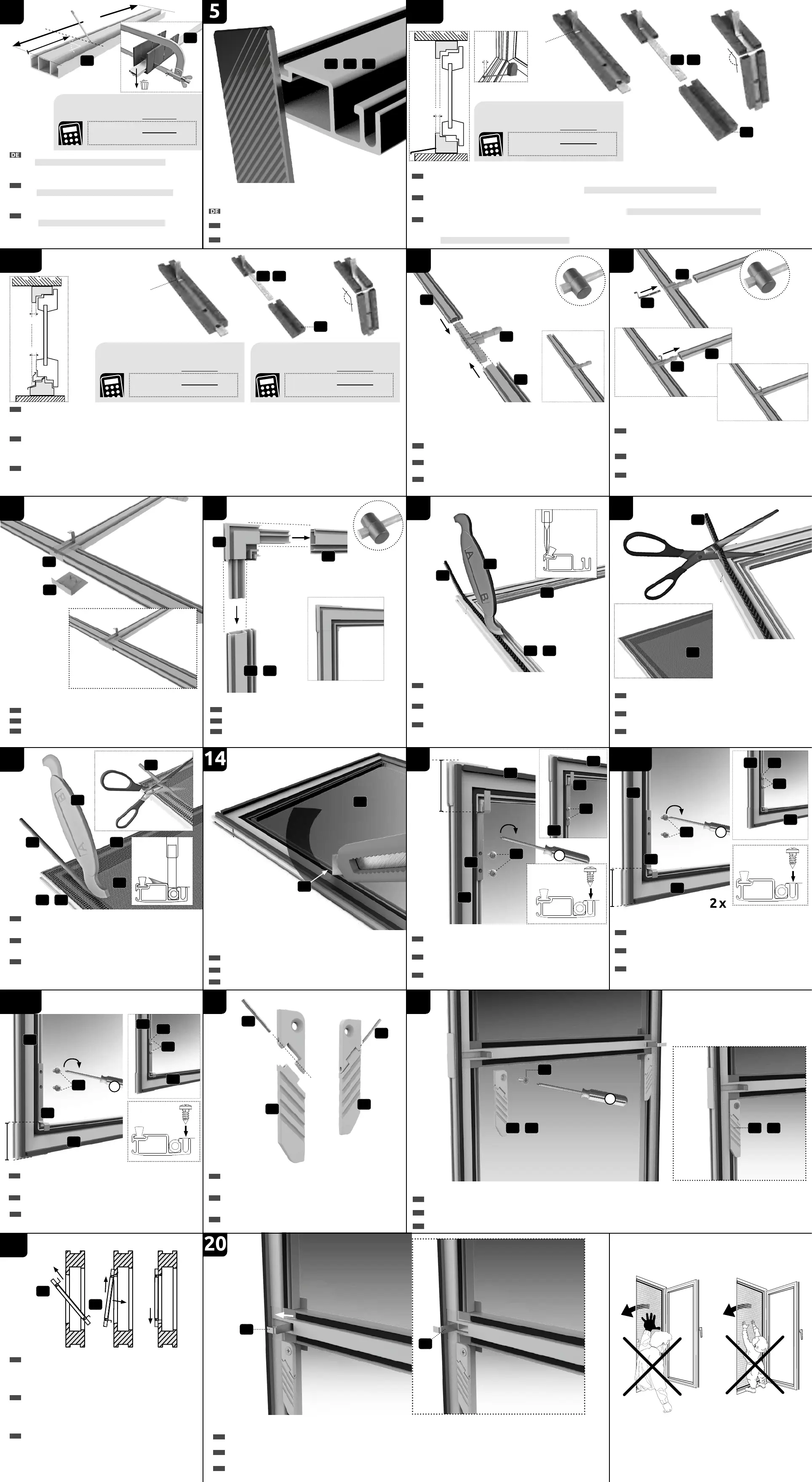
Ermitteln Sie die Blendrahmenstärke X (äußerster Teil des Fensterrahmens) Ihres Fensters mittels Maßbandes. Biegen Sie die Einhängefedern 5a und 5b mittels Biegeschablone
5c auf das ermittelte Maß zuzüglich 3 mm. Legen Sie dazu die Einhängefedern 5a und 5b wie abgebildet in die Biegeschablone 5c und kanten Sie diese im 90° Winkel. Die Skala des
zu biegenden Maßes liegt dabei an der Innenkante der Einhängefeder. Beispiel: Gemessene Blendrahmenstärke X = 14 mm + 3 mm = 17 mm
FR
Établir l’épaisseur du dormant X (partie la plus extérieure du cadre de la fenêtre) de votre fenêtre à l’aide d’un mètre à ruban. Cintrer les quatre ressorts de xation 5a et 5b à
l’aide du dispositif de cintrage 5c sur la mesure déterminée plus 3 mm. Pour ce faire, poser les ressorts de xation 5a et 5b tel qu’illustré sur le dispositif de cintrage 5c et les border
dans un angle de 90°. L’échelle de la mesure à cintrer se trouve au bord intérieur du ressort de xation.
Exemple : Épaisseur du dormant mesuré X = 14 mm + 3 mm = 17 mm
EN
Calculate the blind frame thickness X (outermost part of the window frame) of your window using a tape measure. Bend the four fastening springs 5a and 5b using the bending
device 5c to the calculated dimension and add 3mm. For this purpose put the fastening springs 5a and 5b into the bending device 5c as shown and bend them to a 90-degree angle.
The scale of the dimension to be bent is located at the inner edge of the fastening spring. Example: Measured blind frame thickness X = 14 mm + 3 mm = 17 mm.
2a
2b
12a
4 x
10
DE
Bringen Sie die Abdeckkappen 12b am Mittelverbinder 12a an.
FR
Fixez les caches 12b sur connecteur central 12a.
EN
Attach the covering caps 12b to the central connector 12a.
7c
7c
7a
7b
FR
Pour des fenêtres disposant de rejets d’eau (par ex. fenêtres en bois), mesurez l’épaisseur du bâti dormant X1 (en haut) et X2 (en bas) du chambranle à l’aide d’un mètre ruban. Le
bâti dormant correspond au jambage extérieur du chambranle lorsque la fenêtre est ouverte. Marquez la dimension du bâti dormant supérieur X1 plus 3 mm sur les ressorts d’accrochage
5a et la dimension du bâti dormant X2 plus 3 mm sur les ressorts de xation 5b. Cintrer les quatre ressorts de xation 5a et 5b à l’aide du dispositif de cintrage 5c sur la mesure
déterminée. Pour ce faire, poser les ressorts de xation 5a et 5b tel qu’illustré sur le dispositif de cintrage 5c et les border dans un angle de 90°.
EN
For windows with a rain guard (e. g. wooden windows) measure the blind frame strength X1 (above) and X2 (below) the window frame with measuring tape. The blind frame is the
outermost frame section when the window is open. Mark the upper blind frame measurement X1 plus 3 mm from the fastening springs 5a and the lower blind frame measurement X2
plus 3 mm from the fastening springs 5b. Bend the fastening springs 5a and 5b using the bending device 5c. For this purpose put the fastening springs 5a and 5b into the bending
device 5c as shown and bend them to a 90-degree angle. The scale of the dimension to be bent is located at the inner edge of the fastening spring.
6B
OPTIONAL
x1
x2
x
90°
5c
5a 5b
5c
5a 5b
X1: .......................... mm
+ 3 mm
= mm
Biegemaß | Bending dimension | Mesure de cintrage
Blendrahmenstärke | Blind frame
thickness | Épaisseur du dormant
X2: .......................... mm
+ 3 mm
= mm
Biegemaß | Bending dimension | Mesure de cintrage
Blendrahmenstärke | Blind frame
thickness | Épaisseur du dormant
X: ............................. mm
+ 3 mm
= mm
Biegemaß | Bending dimension | Mesure de cintrage
Blendrahmenstärke | Blind frame
thickness | Épaisseur du dormant
B
–
26
mm
90°
4
4
B: ............................. mm
– 26 mm
= mm
Schnittmaß | Trim size | Dimensions de coupe
Maß | Measurement | Dimensions
1 2a
/
4
/
Markieren Sie an dem Mittelprol 4 das Maß B abzüglich 26 mm.
Beispiel: Gemessene lichte Breite B = 1100 mm - 26 mm = 1074 mm.
Kürzen Sie das Mittelprol an den markierten Stellen mit einer Metallsäge.
Achtung: Verletzungsgefahr! Verwenden Sie die Säge vorsichtig.
EN
Mark the middle section 4 with measurement B minus 26 mm.
Example: Measured clearance width B = 1100 mm – 26 mm = 1074 mm.
Shorten the middle section at the marked sections with a metal saw.
Note: Risk of injury! Use the saw with caution.
FR
Marquez sur le rail de guidage 4 la dimension B moins 26 mm.
Exemple : Largeur libre mesurée B = 1100 mm – 26 mm = 1074 mm.
Raccourcissez le rail de guidage à l’endroit marqué avec une scie métallique.
Attention : risque de blessure ! Utilisez la scie avec précaution.
Entgraten Sie die Schnittächen an den Prolen 1, 2a und 4 mit einer Feile.
DE
Verbinden sie die Höhenprole 2a und 2b über den Mittelverbinder 12a.
Verwenden Sie einen Gummihammer.
EN
Connect vertical proles 2a and 2b via the central connector 12a.
Use a rubber mallet.
FR
Reliez les prolés de hauteur 2a et 2b à l’aide du connecteur central 12a.
Utilisez à cet effet un marteau en caoutchouc.
DE
Legen Sie jeweils eine Einhängefeder 5b in die dafür vorgesehene Ausnehmung der
Mittelverbinder 12a ein. Verbinden Sie die Mittelverbinder 12a mit dem Mittelprol 4.
Verwenden Sie einen Gummihammer.
EN
Insert the suspension springs 5b into the dedicated recess in the middle corner
12a. Connect the middle corners 12a with the middle section 4. Use a rubber mallet.
FR
Insérez les ressorts xation 5b en bas dans l’évidement prévue à cette n sur le
connecteur central 12a. Connectez les connecteur central 12a au prol central 4.
Utilisez à cet effet un marteau en caoutchouc.
5b
12a
10
11
12a
12b
12a
4
9
3
1
4 x
DE
Verbinden Sie die Prole 1 und 2a / 2b mittels Eckverbinder 3 zu einem Rahmen.
EN
Connect the sections 1 and 2a/2b with corner connectors 3 to a frame.
FR
Reliez ensemble les prolés 1 et 2a/2b par le biais d’un raccord d’angle 3 pour
en faire un cadre.
2b2a
/
9
8
1
2a 2b
/
DE
Setzen Sie die Dichtungsbürste 9 an der äußeren oberen Prolnut der Prole 1 und
2a/2b an und drücken Sie diese mit der schmalen Spitze B des Kederwerkzeugs 8 in die Nut.
EN
Place the sealing brush 9 on the outward upper groove of sections 1 and 2a/2b
and press it with the thin tip B of the welt tool 8 in die groove.
FR
Placez la brosse d’étanchéité 9 contre la rainure de prolé supérieure extérieure des
prolés 1 et 2a/2b et poussez ces prolés avec la pointe étroite B de l’outil à bourrelet 8
dans la rainure.
9
11
12
1817
19
DE
Kürzen Sie die Dichtungsbürste 9 entsprechend der Nutlänge mit einer Schere.
Rollen Sie das Gewebe 11 über den Rahmen aus.
EN
Shorten the sealing brush 9 with scissors to match the recess length. Roll the
material 11 over the frame.
FR
Raccourcissez la brosse d’étanchéité 9 avec des ciseaux en fonction de la
longueur de rainure. Déroulez le tissu 11 par dessus le cadre.
10
10
8
11
1
2a 2b
/
1514
DE
Fixieren Sie das Gewebe 11 mittels Gummikeder 10 in der Kedernut der Prole 1,
2a / 2b und 4. Verwenden Sie dazu die breite Seite A des Kederwerkzeugs 8. Kürzen Sie
den Keder 10, nachdem Sie diesen umlaufend befestigt haben, mit einer Schere.
EN
Attach the material 11 with a rubber welt 10 to the welt groove 1, 2a/2b and 4.
Use the wide side A of the welt tool 8 to do this. Shorten the welt 10 with scissors after
you have attached it all around.
FR
Fixez le tissu 11 à l’aide du bourrelet en caoutchouc 10 dans la rainure de
bourrelet des prolés 1, 2a/2b et 4. Utilisez à cette n le côté large A de l’outil à
bourrelet 8. Raccourcissez le bourrelet 10 avec des ciseaux une fois que vous l’avez xé
sur toute la périphérie.
11
10
DE
Kürzen Sie das Gewebe 11 außen entlang des Keders 10 mit einem Cutter.
EN
Shorten the material 11 outside along the welt 10 with a cutter.
FR
Raccourcissez le tissu 11 à l’extérieur le long du bourrelet 10 à l’aide d’un cutter.
DE
Verbinden Sie jeweils die linken und rechten Griffteile zu den Einheiten 7a und 7b
miteinander und stecken Sie die Metallstifte 7c zur Verbindung in die Ausnehmung.
EN
Link the left and right grip elements to the units 7a and 7b and insert the metal
pins 7c into the recesses to connect.
FR
Reliez ensemble les pièces de poignée gauche et droite pour en faire les unités 7a et
7b et enfoncez les tiges de métal 7c dans l’évidement pour les raccorder l’une à l’autre.
DE
Schrauben Sie die Griffe 7a und 7b links und rechts mittels Schrauben 7d in die Schraubnut der Rahmenprole 2b.
EN
Screw the grips 7a and 7b left and right with screws 7d into the screw groove of the frame sections 2b.
FR
Vissez les poignées 7a et 7b gauche et droite à l’aide de vis 7d dans la rainure de vis des prolés de cadre 2b.
+
20
1. 2. 3.
5a
5b
7a 7b
/
7a 7b
/
DE
Der Insektenschutz ist nun bereit zum Einhängen. Öffnen Sie Ihr Fenster und führen
Sie den Insektenschutzrahmen nach außen. Führen Sie die oberen Einhängewinkel 5a von
außen in den Blendrahmen. Ziehen Sie den Rahmen heran und schieben Sie ihn nach
unten, sodass die unteren Einhängefedern 5b hinter den Blendrahmen greifen. Achten Sie
auf Ihre Sicherheit und lehnen Sie sich nicht aus dem Fenster – Absturzgefahr!
EN
The insect screen is now ready for mounting. Open your window and place your
insect screen frame. Guide the upper suspension hooks 5a into the blind frames from
outside. Pull the frames in and push them out so the the lower suspension springs 5b
attach behind the blind frame. Stay safe and do not lean out of the window – danger of
falling!
FR
La moustiquaire est désormais prête à être accrochée. Ouvrez votre fenêtre et
guidez le cadre de la moustiquaire vers l’extérieur. Insérez les équerres d’accrochage
supérieurs 5a de l’extérieur dans le bâti dormant. Tirez le cadre vers vous et poussez-le
vers le bas, an que les ressorts d’accrochage inférieurs 5b viennent en prise derrière le
bâti dormant. Veillez à votre sécurité et ne vous penchez pas par la fenêtre – Risque
de chute !
DE
Schieben Sie die Einhängefedern 5b in den Mittelverbindern 12a nach außen und xieren so das Fenster mittig.
EN
Push the xation springs 5b outwards in the middle connectors 12a and thus x the window in the middle.
FR
Poussez les ressorts de xation 5b vers l’extérieur dans les connecteurs central 12a et xez ainsi la fenêtre au milieu.
2a
5a
36 mm
1
2 x
+
2 x
2a
1
5a
6
90°
6
13
DE
Fixieren Sie die oberen Einhängefedern 5a mit einem Abstand von 36 mm zum
Rahmen mittels der Schrauben 6. Vorsicht: überdrehen Sie die Schrauben nicht.
EN
Attach the upper suspension springs 5a 36 mm away from the frame with the
screws 6. Careful: do not over-tighten the screws.
FR
Fixez les ressorts d’accrochage inférieurs 5a avec une distance de 36 mm par
rapport au cadre à l’aide des vis 6. Attention : ne faussez pas les vis.
7d
2 x
2b
2b
5b
1
1
30 mm
+
6
6
16A
DE
Fixieren Sie die unteren Einhängefedern 5b mit einem Abstand von 30 mm zum
Rahmen mittels der Schrauben 6. Vorsicht: überdrehen Sie die Schrauben nicht.
EN
Attach the lower suspension springs 5b 30 mm away from the frame with the
screws 6. Careful: do not over-tighten the screws.
FR
Fixez les ressorts d’accrochage inférieurs 5b avec une distance de 30 mm par
rapport au cadre à l’aide des vis 6. Attention : ne faussez pas les vis.
2 x
2b
5b
5b
1
Z
+
2 x
6
2b
1
6
5b
16B
OPTIONAL
DE
Fixieren Sie die unteren Einhängefedern 5b mit dem ermittelten Abstand z
(z. B. 50 mm) zum Rahmen mittels der Schrauben 6. Vorsicht: überdrehen Sie die
Schrauben nicht.
EN
Attach the lower suspension springs 5b with the determined distance z
(e. g. 50 mm) to the frame with the screws 6. Careful: do not over-tighten the screws.
FR
Fixez les ressorts d’accrochage inférieurs 5b avec la distance déterminée
(par ex. 50 mm) par rapport au cadre à l’aide des vis 6. Attention : ne faussez pas les vis.
5b
6A
5b
 Loading...