WaterBug
®
Model WB-200
Part No. M-001-0104
Installation / Owners Manual
Introduction
® ®
Thank you for your purchase of the Winland WaterBug model WB-200. The WaterBug is completely electronic and is designed to detect water only (distilled
and de-ionized water cannot be detected). The unit is not a self contained warning device. For proper operation this unit must be used in conjunction with an
alarm system, wireless transmitter, etc. It is designed so that the control console mounts on a wall or other flat vertical surface and the remote probes are placed
in the locations where water leakage is most probable. Up to six remote sensors may be connected to one control console. A film of moisture forming a bridge
between the two metallic contacts on any remote sensor is all that is needed for the unit to signal an alarm condition. The output on the WB-200 is non-latching,
but will remain closed until the moisture bridge is broken. As sensitive as the WaterBug
®
is, it will not alarm due to high humidity or condensation. The
WaterBug
®
is ideal for use in homes, offices, computer rooms, boats, etc. Several consoles may be wired together to monitor an entire complex.
Installation
®
Locate the area where the WaterBug
console is to be mounted. Mark the position of the screw hole on the mounting surface. Drive the mounting screw into
the wall allowing 3/16” between the screw head and the wall. Engage the key slot on the back of the WaterBug
®
console and the screw head and press down.
Multiple sensors must be hooked up in parallel to terminals 3 & 4. The remote surface sensors may be mounted securely to the floor or a wall. Mounting the
sensor(s) to a vertical surface like a wall enables you to monitor an area for rising water levels. This is useful in basement sump pumps and other types of water
storage and drainage systems.
Monitoring for the Absence of Water
®
The WaterBug
model WB-200 can be used to monitor for the absence of water. This is done by (a) mounting the probe at the desired minimum waterline and
(b) using the set of relay contacts that are the opposite of what you would use if you were detecting the presence of water.
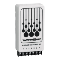
Terminal Block Connections
Relay contacts are accessible on the terminal block (See Figure 1). The unit is in normal condition when power is applied and no moisture is being detected.
The unit is in alarm condition when water is detected by any one of the remote sensing probes. Note: When connecting DC power to the WB-200 be sure to
observe polarity and test to see if the unit is operating properly. This may be done by forming a moisture bridge between two of the metallic contacts located on
the sensor probe (See Figure 2) with a moistened finger or cloth. If the unit is not operating properly, check the polarity of the power supply connections.
AC – Power input wires are interchangeable
DC – Positive to Position #1 and negative to Position #2
The relay connections shown are for when power is applied to the
unit. The unit provides power-on supervision so that if power is lost,
the relay will provide an alarm output.
If using for detecting the absence of water, the NC and NO contacts
will be reversed.
GROUND ( - VAC / VDC)
RELAY - NC
RELAY - NO
RELAY - COMMON
PROBE
Fi
ure 1
Test Procedures
To test the unit’s operational status, form a moisture bridge between the two metallic contact points (See Figure 2) with a moistened finger or cloth. If working
properly, the WaterBug
®
will activate the warning device to which it is connected within approximately three seconds. The unit will reset automatically when the
probe dries and there is no longer a moisture bridge between the two metallic contact points
Standard Surface Sensor
If a remote sensor is to be bolted down in a permanent installation, do not drill any hole outside of the innermost center recessed area (See Figure 3). Damage
to the internal wiring may occur, causing the unit to fail.
Figure 2