4 BlackBox and WhiteBox F-1
14 W-DMX G4(S) User Manual, edition 2 2013-10
Phoenix gold connector 12 V DC:
• Left: Ground
• Right: +12 V DC
5 Cord Strip For signal cable (DMX or Ethernet)
6 DMX IN / OUT RJ 45 port:
for Universe 1
(depeding on
production date)
• Middle: DMX Data – (for Universe 1)
• Right: DMX Data + (for Universe 1)
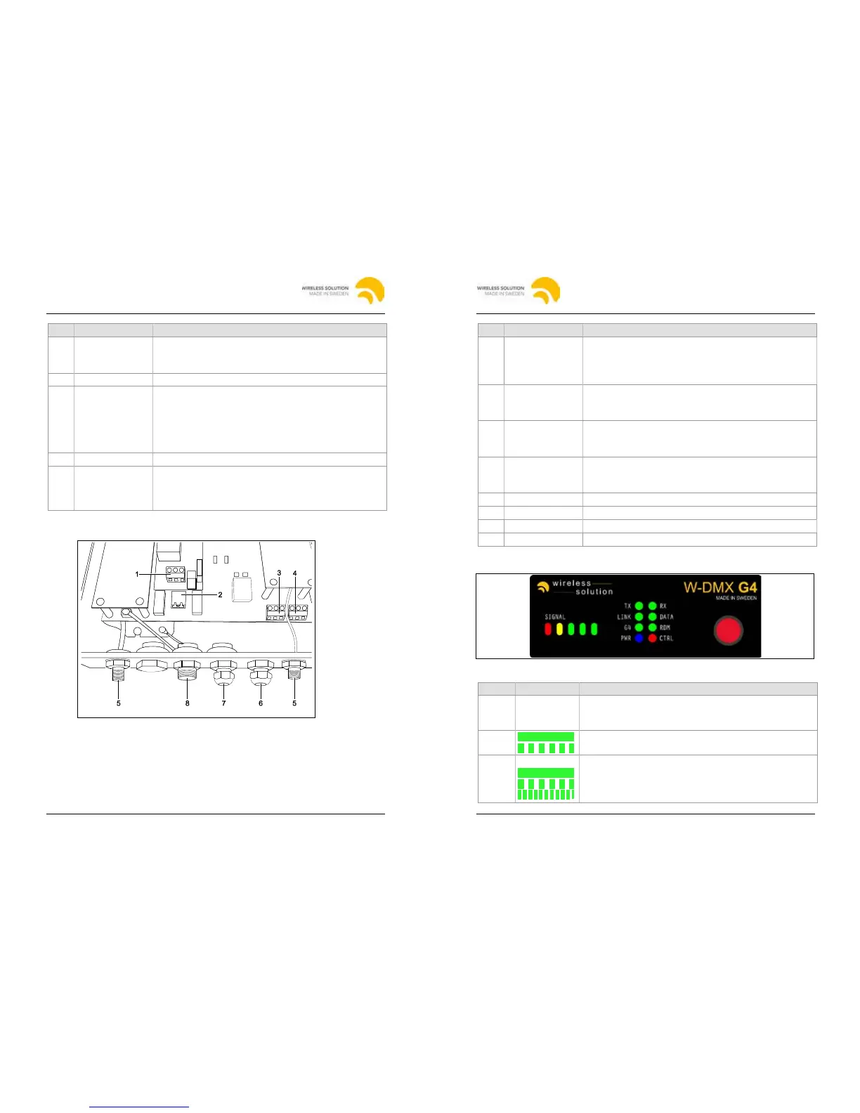
4.2.3 WhiteBox F-1 MK II
Fig. 4: Connectors and ports of the WhiteBox F-1 MK II
To ensure safe transmission of signals for outdoor use, the WhiteBox does not
have XLR connectors. For this reason the connection of DMX signal cables
differs slightly from the BlackBox models, which are for indoor use only.
To install the unit it is necessary to open the housing. See
chapter "4.4.2 WhiteBox F-1", page 17.
4 BlackBox and WhiteBox F-1
2013-10 W-DMX G4(S) User Manual, edition 2 15
• Left: Outer conductor (L)
• Middle: Ground (GND)
• Right: Neutral conductor (N)
2 DC power input Phoenix gold connector U
DC
= 12 V:
• Left: Ground
3 DMX OUT
for Universe 1
• Left: GND
• Middle: DMX Data – (Universe 1 OUT)
• Right: DMX Data + (Universe 1 OUT)
• Middle: DMX Data – (Universe 1 IN)
• Right: DMX Data + (Universe 1 IN)
5 Antenna ports Connector for antennas
6 Cord Strip For signal cable (DMX or Ethernet)
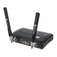
4.3 LEDs
Fig. 5: LEDs of F-1
RX (receiver) mode: Currently received signal strength
TX (transmitter) mode: Yellow and green LEDs indicate
• Flashing: Transmitter in repeater mode
• On: Normal operation
• Flashing: Receivers are being unlinked
• Rapid flashing: Receivers are being linked
2014-03 W-DMX G4(S) User Manual, edition 32014-03
W-DMX G4(S) User Manual, edition 3