Place the base seal over threaded section and feed through bottom of
cistern. Secure hand-tight plus half a turn using back-nut supplied
(using a suitable spanner). Shown below are bolted and plated kit
assemblies for close coupled WC pans and cisterns.
BOLTED KIT PLATED KIT
Back-Nut
Cistern Base
Plate
WC Pan
Bolt
Rubber Washer
Metal Washer
Finger Nut
1
Bolt
Plastic Sleeve
Plastic Washer
Cistern
Plastic Washer
Metal Nut
Pan
Plastic Washer
Metal Wing Nut
Important for new installations : before turning water on,
ensure that one cold water tap is open so that dirt and loose
particles in the pipe work are flushed through the tap (we
also recommend to flush through the water supply pipe to the
cistern before connection is made.
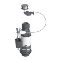
INLET VALVE
▼
Assembly instruction leaflet
• Jollyfill telescopic bottom entry inlet valve
SANITARY EQUIPMENT SPECIALIST
- Fit the filling valve. Ensure that the valve does not obstruct the
flush mechanism. Do not overtighten the back nut.
2
If pressure < 1 bar (15 p.s.i) :
cut here (gravity pressure/ header tank)
A : PRE-INSTALLATION
B : INSTALLATION
Turn off water supply to cistern and remove cistern
lid.
Flush the cistern and remove any loose dirt from
inside the tank.
Disconnect and remove the existing inlet valve.
Insert correct filter restrictor into threaded tail.
1
2
3
1
- Fit the filling valve. Ensure that the valve does not obstruct the
flush mechanism. Do not overtighten the back nut.
2
If pressure < 1 bar (15 p.s.i) :
cut here (gravity pressure/ header tank)
Fit the filling valve. Ensure that the valve does not obstruct
the flush mechanism. Do not overtighten the back nut
.
2
3
Connect water supply.
4
JOLLYFILL TELESCOPIC
BOTTOM ENTRY INLET VALVE
!
Turn on water supply. Allow the cistern to fill,
5
Adjust the water level,
A
Waterline
Internal overflow
2 cm
25 mm minimum
from internal overflow to
critical level (CL)
min 0 to
max
150mm
If the water level is not correct, turn off water supply.
Adjust the water level by : Turning slowly right or left to open.
Pulling up the body of the telescopic part, (see pic B).
Turning slowly right or left to lock. Turn on water supply.
B
B
A
Waterline
Internal overflow
2 cm
25 mm minimum
from internal overflow to
critical level (CL)
NOT OKOK
A
min 0 to
max
150mm
on inlet valve.
C
You can precisely adjust the float basin
with the red rod. Unclip the red rod
Adjust the float basin Clip the red rod.
C
Waterline
Internal overflow
2 cm
25 mm minimum
from internal overflow to
critical level (CL)
NOT OKOK
A
min 0 to
max
150mm
on inlet valve.
TROUBLE SHOOTING MAINTENANCE
FOR JOLLYFILL SIDE AND BOTTOM ENTRY VALVES
!
Turn off water supply before any maintenance is carried out.
A
B
2
2
Remove and wash
the diaphragm
and reassemble in
reverse order.
3
Remove and wash
the filter restrictor
and reassemble in
reverse order.
3
If pressure < 1 bar (15 p.s.i.) :
cut here (gravity pressure / header tank)
Adjustment rod
Float
Float basin
Threaded tail
Rubber washer
Back nut
Filter restrictor
!
NOT OKOK