Do you have a question about the wirsbo WT Series and is the answer not in the manual?
Provides 24VAC+/-10% for operation.
Supports 1.3A @ 24VAC, with specific ratings for MVA and TVA control devices.
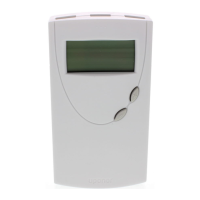
Displays room temperature from 32-99°F and allows setpoints from 40-99°F.
Handles shipping temps from -10-70°C and ambient temps from 0-40°C, with 40-90% non-condensing humidity.
Compact size of 5.0"H x 2.72"W x 0.91"D, weighing 0.22 lbs.
Digital thermostats specifically for hydronic radiant heating applications, with a 3-wire model (A3030103) for heat only.
Eliminates voltage drop, provides full 24V, and uses a dry contact for heat demand switching (R & W terminals).
Requires familiarity with product, suitability check, professional installation, and use of 18AWG wiring.
Install 5 feet above floor on smooth surface, avoiding windows, outside walls, fireplaces, corners, and drafty areas.
Instructions for separating plates, mounting wallplates, and wiring connections, emphasizing power disconnection.
Use '+' and '-' buttons to adjust room temperature; changes are accepted after 5 seconds.
Switch between heating and off modes by pressing both buttons simultaneously.
Utilizes Differential (1°F below setpoint) and Pulse Width Modulation (PWM) for nuanced temperature management.
Smoothes temperature readings by filtering erratic values, ensuring stable operation and display.
| Brand | wirsbo |
|---|---|
| Model | WT Series |
| Category | Thermostat |
| Language | English |