© 2004 Wohler Technologies Inc. ALL rights reserved
8
AMP2-DA/AVU and AMP2-DA/APP User Manual P/N 821584 Rev-A
6
7
8
4
5
1
2
3
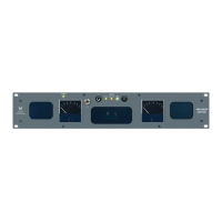
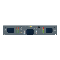
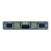
Please refer to Figure-2a on the facing page to familiarize yourself with the front panel features of the AMP2-DA/AVU and AMP2-
DA/APP units. The following sections describe these features and are referenced, by number, to Figure-2a.
Front Panel Features
Section 2: Operation
(Continued)
Speakers
The monitor features two mid-range speakers (left and right) and one woofer speaker. Two amplifier/driver combinations
handle midrange and high frequency information in the left and right (stereo) speaker channels, while the third channel
reproduces and sums the left and right channel information below the 500 Hz crossover point in the woofer (bass) speaker(s).
Note that the woofer channel is NOT a dedicated LFE (subwoofer) or Center channel. See page 16 for more information
concerning the AMP2 Series audio amplifier/speaker configuration.
Audio Level Meters - Mechanical
Audio levels for the left and right sources selected for monitoring are respectively displayed in the left and right mechanical
level meters. The AMP2-DA/AVU model uses meters exhibiting VU ballistic characteristics. The AMP2-DA/APP model
uses meters exhibiting PPM ballistic characteristics. See page 21 for Threshold Level adjustment and settings for the VU
and PPM type of meter.
Analog/Digital Source Select Switch
This two position toggle switch allows the operator to choose between two primary input sources; ANALOG or DIGITAL
• ANALOG = Unit will monitor the analog signals as input on the rear panel ANALOG IN XLR connectors (Item F,
page 14).
• DIGITAL = The unit will monitor the AES signals as input on the selected (1 or 2) rear panel AES/EBU IN BNC
connector (Item C, page 12).
AES Source Select Switch (1 or 2)
This two position toggle switch allows the operator to choose between the two rear panel AES/EBU IN digital input
connectors; 1 or 2 (Item C, page 12). Note that in order to monitor the selected AES input, the Analog/Digital Source
Select Switch (Item 3) must be set to DIGITAL.
AES Status LED
This bi-color (GREEN/RED) LED indicates the status of the selected AES input signal (1 or 2) and functions regardless of
whether the analog or AES inputs are selected for monitoring. LED indication is as follows:
• GREEN = a valid AES/EBU digital datastream is being received
• RED = there are errors in signal reception and/or data errors (if the data has been tagged as inappropriate for
conversion to analog by having the validity bit set).
Note: The AES Termination and Error Indication Type DIP switch module on the rear panel (Item B, page 12) is used
to set this LED to indicate either reception and data errors or to indicate reception errors only.
An optional feature of the AES signal error detection is the ability to mute the audio when errors are detected in the AES
signal. To enable this feature, a jumper is placed at H12 of the 919117 PCB. See page 20 for location of H12 on the
919117 PCB.
Headphone Jack
This jack accepts a standard 1/4” phone type stereo plug. Select the headphone audio sources as you would for the internal
speakers. When you plug in headphones, the speakers will mute.
Volume Control
This controls the loudness of the audio reproduced by the internal speakers or connected headphone. Clock-wise rotation
of this control increases the loudness of the monitored audio.
Power LED
This LED glows GREEN to indicate the unit is connected to mains power and an operation voltage is present.