Component Removal
Integrated Modules
Integrated Modules
3-13
#826498 - Revision B - December, 2016
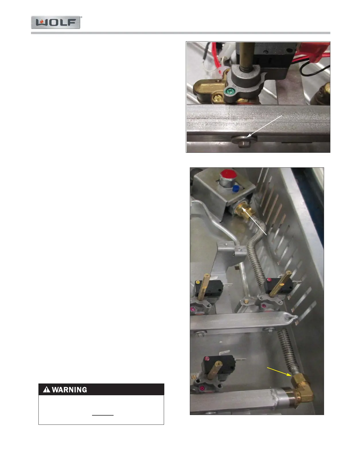
Burner Valve Removal
To remove the burner valve, first remove the display
light board then, (See Figure 3-22):
Remove black wire from NO terminal.1.
Remove red wire from C terminal.2.
Use 5/16” open end wrench to remove simmer3.
burner tube.
Use 1/2” open end wrench to remove main burner4.
tube.
Use 1/4” box wrench to remove manifold screw.5.
NOTES:
If gas tubes are difficult to remove from the valve,•
remove gas tubes from orifice holder and remove the
burner valve with gas tubes attached. Then remove
gas tube from valve.
Do not lift manifold to remove tube fittings. Gas tubes•
provide support to the manifold. Deforming gas tube
may cause knob alignment issues.
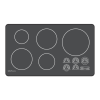
Regulator Removal
To remove the regulator, first remove the burner pan
then, (See Figure 3-23):
Disconnect external gas supply line to inlet of1.
regulator from 1/2” NPT nipple.
Use a 5/8” open end wrench to remove regulator2.
outlet line from brass fitting.
Use a 7/16” open end wrench to remove ground3.
retaining nut from regulator bracket.
Remove regulator and regulator bracket together.4.
Use a 7/8” box wrench to remove brass fitting5.
from the regulator outlet.
Manifold Removal
To remove the manifold first remove the display light
board, then (See Figure 3-23):
Remove all gas valves from the manifold.1.
Use a 5/8” open end wrench to remove manifold inlet2.
line from brass elbow on manifold.
NOTES:
Regulator in Figure 3-23 is identified as an LP regula-•
tor by its red cap.
It is unnecessary to remove gas lines or switch wiring•
from burner valves to replace the manifold.
Manifold is supported by burner valve gas lines.•
Adjustment of gas line configuration could cause valve
alignment issues.
Brass elbow included on new manifold.•
Figure 3-23. Regulator and Manifold
Figure 3-22. Burner Valve
WHEN REASSEMBLING MANIFOLD COMPO-
NENTS, ONLY PIPE THREAD COMPOUND
SHOULD BE USED. DO NOT USE TEFLON
TAPE TO SEAL GAS CONNECTIONS
Regulator
Manifold
Inlet Line
1/4” Manifold
Screw