Do you have a question about the Wolf CWL-300 Exxellent and is the answer not in the manual?
Lists relevant standards and regulations for ventilation systems.
Explains the applicability and personnel requirements for the service instructions.
Defines the meaning of symbols used throughout the instruction manual for safety and notes.
Details safety warnings, electrical hazards, and the need for qualified personnel.
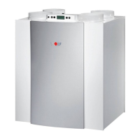
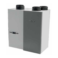
Describes the purpose of the CWL CWL Excellent ventilation unit as a central ventilation system.
Specifies the correct applications and limitations for the ventilation unit.
Outlines requirements for the location where the appliance should be installed.
Provides guidance on how to operate the appliance and any necessary precautions.
Covers essential maintenance tasks and procedures for the unit.
Explains the environmentally responsible methods for disposing of the appliance.
Lists all components included with the heat recovery unit upon delivery.
Provides detailed technical specifications for the CWL-300 Excellent model.
Presents fan performance data for the CWL-300 Excellent in a graphical format.
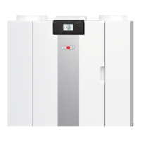
Details the technical specifications for the CWL-400 Excellent model.
Shows fan performance characteristics for the CWL-400 Excellent model graphically.
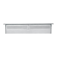
Illustrates connection points and dimensions for the right-handed unit.
Illustrates connection points and dimensions for the right-handed unit.
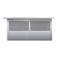
Shows connection details and dimensions for the left-handed unit.
Provides a detailed breakdown of the appliance components with numbering.
Gives a general overview of the appliance's automatic operation and functionality.
Explains the conditions under which the bypass valve opens and closes.
Describes the intelligent frost protection system and its operation.
Mentions connection options for different appliance versions.
Outlines general guidelines and requirements for appliance installation.
Details the correct placement and mounting procedures for the unit.
Explains how to connect the condensate discharge line correctly.
Provides instructions for connecting the air supply and extract ducts.
Guides on connecting the appliance to the main power supply.
Guides on connecting the appliance to the main power supply.
Explains how to connect a multiple switch for control purposes.
Details the process for connecting the eBus connector for system integration.
Describes the LCD display and control keys on the appliance's panel.
Explains how to interpret the display during normal operation.
Guides the user through accessing and modifying appliance settings.
Explains how to view current sensor values and operating data.
Details how to access and interpret service and fault messages.
Explains the fan status indicators shown on the display.
Describes how the air flow rate is shown on the appliance display.
Lists and explains various message texts that can appear on the display.
Provides step-by-step instructions for modifying settings via the menu.
Details how to navigate and read sensor values from the readout menu.
Explains how to access and interpret fault messages in the service menu.
Describes the procedures for turning the appliance on and off using software or power plug.
Guides on setting the desired air flow rates for different operation modes.
Refers to other configurable settings available for installers.
Explains how to reset all settings back to their original factory configuration.
Provides guidance on identifying and resolving common faults indicated by the appliance.
Explains the meaning of different fault codes and symbols shown on the display.
Details the steps for cleaning or replacing the appliance filters.
Covers installer-specific maintenance tasks like heat exchanger and fan cleaning.
Presents a general overview of the electrical connections and components.
Shows the detailed wiring connections for the appliance's electrical system.
Describes various connectors (X1, X2, X14, X15) and their functions.
Illustrates different ways to connect multiple switches and remote controls.
Explains how to connect multiple units using the eBus for synchronized operation.
Shows wiring for connecting a postheater or extra preheater.
Details how to connect a geo heat exchanger to the system.
Guides on connecting external switch contacts for additional control.
Explains how to connect devices using a 0-10 V signal input.
Describes how to connect a humidity sensor to the unit.
Provides a visual exploded view of the appliance's components.
| Airflow | 300 m³/h |
|---|---|
| Power consumption | 30 W |
| Mounting | Ceiling mounted |
| Power | 30 W |
| Frequency | 50 Hz |
| Voltage | 220-240 V |