Do you have a question about the Wolf CWL-2-325 and is the answer not in the manual?
Details the components included in the delivery package of the heat recovery appliance.
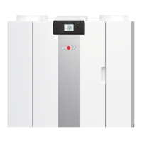
Provides detailed technical specifications, dimensions, and performance data for the CWL -2-325 appliance.
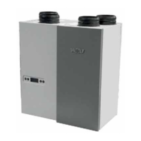
Outlines the connection ports and physical dimensions for both left-hand and right-hand versions of the appliance.
Presents a detailed exploded view of the appliance, identifying all components and their respective numbers.
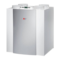
Explains the basic functionality and features of the ventilation unit and its control system.
Details the 100% bypass function, its purpose, and the conditions for automatic opening and closing of the bypass valve.
Describes the appliance's frost protection control mechanism, which uses temperature sensors and a preheater.
Explains the 'Plus' version with an extra control board offering more connections and functionalities.
Outlines general requirements and steps for installing the appliance, including quality and regulatory considerations.
Covers the requirements for mounting the appliance, including wall type, placement, and required clearances.
Details the connection of the siphon and condensate discharge line, including important warnings and recommendations.
Provides instructions and recommendations for airtight installation of air ducts, noise reduction, and air speed limits.
Covers various electrical connection types for accessories and system integration of the appliance.
Introduces the touchscreen display, its function for operation and status information, and the main screen layout.
Explains the division of the screen into zones and the meaning of various symbols and displays shown on the main screen.
Describes how the display indicates status, filter messages, faults, and how to navigate menus and adjust settings.
Provides instructions for powering the appliance on and off, including initial startup procedures and warnings.
Explains how to adjust the air flow rate for optimal ventilation, mentioning factory settings and control options.
Mentions the possibility of changing other appliance settings for installers, referring to specific pages for details.
Describes how to revert all changed settings back to the appliance's original factory configuration.
Explains how faults are indicated on the display via a spanner symbol and fault numbers, distinguishing between limited and locking faults.
Details non-locking and locking faults, including their display indications and potential causes/solutions.
Guides on cleaning or replacing filters, including indicators, frequency, and the use of a filter wizard.
Explains the annual requirement to disconnect and clean the appliance's siphon.
Details installer maintenance tasks like cleaning the heat exchanger, preheater, and fans, typically done every three years.
Explains how to connect a multiple switch, recommending a 4-way switch with filter indication.
Guides on connecting the BM-2 control unit using two-core control cables and the eBus connector.
Details the connection of an optional humidity sensor, including the cable and its placement on the basis pcb.
Explains how to connect CO2 sensors, including cabling, connectors, and settings for PPM values.
Shows the electrical connections for an optional postheater, including heating coil, safety reset, and temperature sensor.
Details the electrical connections for an optional preheater, including heating coil, safety reset, and dipswitch settings.
Explains that when ordering parts, appliance type, serial number, year of production, and part name are needed.
Lists factory settings and ranges for various parameters of the standard CWL -2-325 appliance.
Lists settings for the CWL -2-325 appliance when equipped with a Plus pcb, covering switch contacts and voltage inputs.