EasyManua.ls Logo

WoodFast PT410A - User Manual

Default Icon
13 pages
Print Icon
To Next Page IconTo Next Page
Loading...
Instruction
Manual
IMPORTANT
For your safety read
instructions carefully
before assembling or
using this product.
Save this manual for
future reference.
Planer & Thicknesser
PT410A
Original Instruction
V.1-201910
/RIGINAL¬)NSTRUCTION¬-ANUAL
6ERSION¬
&EBRUARY¬
7OODWORKING¬-ACHINES¬¬!CCESSORIES
4ELEPHONE¬¬¬
&AX¬¬¬
3TARTRITE
5NIT¬"¬!DELPHI¬7AY
3TAVELEY¬¬3¬,3
%MAIL¬SALES RECORDPOWERCOUK
WWWSTARTRITECOUK
%¬%¬¬%¬¬¬
)NDUSTRIAL¬¬
"ANDSAW
)-0/24!.4
&OR¬YOUR¬SAFETY¬READ¬INSTRUCTIONS¬CAREFULLY¬BEFORE¬
ASSEMBLING¬OR¬USING¬THIS¬PRODUCT¬3AVE¬THIS¬
MANUAL¬FOR¬FUTURE¬REFERENCE
(%!,4(¬!.$¬3!&%49¬'5)$%,).%3
!LWAYS¬FOLLOW¬THE¬INSTRUCTIONS¬PROVIDED¬WITH¬THE¬MANUAL¬!LWAYS¬WEAR¬SAFETY¬GLASSES¬WHEN¬USING¬WOODWORKING¬
EQUIPMENT¬!LWAYS¬DISCONNECT¬THE¬POWER¬BEFORE¬ADJUSTING¬ANY¬EQUIPMENT¬&AILURE¬TO¬OBSERVE¬PROPER¬SAFETY¬
PROCEDURES¬AND¬GUIDELINES¬CAN¬RESULT¬IN¬SERIOUS¬INJURY
7!2.).'¬$O¬NOT¬ALLOW¬FAMILIARITY¬GAINED¬FROM¬FREQUENT¬USE¬OF¬YOUR¬MACHINE¬AND¬ACCESSORIES¬TO¬BECOME¬
COMMONPLACE¬!LWAYS¬REMEMBER¬THAT¬A¬CARELESS¬FRACTION¬OF¬A¬SECOND¬IS¬SUFlCIENT¬TO¬INmICT¬SEVERE¬INJURY
!LWAYS¬WEAR¬SAFETY¬GLASSES¬WHEN¬
USING¬WOODWORKING¬EQUIPMENT
!LWAYS¬READ¬THE¬INSTRUCTIONS¬
PROVIDED¬BEFORE¬USING¬
WOODWORKING¬EQUIPMENT
Question and Answer IconNeed help?

Do you have a question about the WoodFast PT410A and is the answer not in the manual?

Overview

This document is a user manual for the WOODFAST PT410A Planer & Thicknesser, a woodworking machine designed for surface planing and thickness planing of solid woods.

Function Description

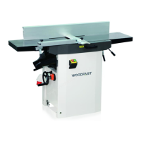
The WOODFAST PT410A is a dual-function machine, capable of both surface planing (jointing) and thickness planing.

  • Surface Planing Mode (Jointing): In this mode, the machine flattens an irregular surface of a workpiece. The workpiece rests on the infeed table and is cut on its underside. The feed direction is opposite to that of thickness planing. The jointer fence provides lateral support for the workpiece.
  • Thickness Planing Mode: This mode is used to reduce a workpiece with one already surface-planed side to a desired thickness. The workpiece is fed through the thicknesser, with the already planed flat surface resting on the thicknesser bed, and the cut is made on the upper side. The feed direction is opposite to that of surface planing.

The machine features a cutterblock with multiple knives that perform the cutting action. A dust chute with a suction connector is installed for thickness planing to manage wood dust. Safety features include a cutterblock guard and an ON/OFF switch with an emergency stop button.

Important Technical Specifications

The PT410A model has the following key specifications:

  • Feed speed: 7 m/min
  • Cutterblock speed: 5000 rpm
  • Cutterblock diameter: 70 mm
  • Max thicknesser capacity: 405x225 mm (width x height)
  • Max planing width: 410 mm
  • Max depth of cut (thicknesser): 3 mm
  • Max depth of cut (planer): 4 mm
  • Number of knives: 3
  • Fence tilting degree: 0-45 degrees
  • Motor power output:
    • 1*230V: 3kW S6
    • 3*400V: 4kW S6
  • Net Weight: 265 kg

Noise Emission: Measurements were carried out under ISO 7960 Annex B and C standards:

  • Sound power level (no load): <98dB(A)
  • Sound power level (load): <107dB(A)
  • Sound Pressure level (no load): <89dB(A)
  • Sound Pressure level (load): <98dB(A)
  • Constant K=4 dB measured in accordance with EN ISO 3746:1995.

Workpiece Dimensions:

  • Surface Planing:
    • Length: For workpieces shorter than 250 mm, a push stick is required. For workpieces over 1500 mm, a second person for support is recommended.
    • Width: max. 410 mm
    • Thickness: min. 5 mm
    • Max. depth of cut for a single pass: 3 mm
  • Thickness Planing:
    • Length: min. 200 mm. For workpieces over 1500 mm, a second person for support is recommended.
    • Width: max. 405 mm
    • Thickness: min 6 mm; max. 200 mm
    • Max. depth of cut for a single pass: 4 mm

Usage Features

  • Installation: The machine can be transported by forklift or by several persons using carrying straps or battens placed underneath the thicknesser bed. It must be fixed to the floor using expansion bolts. Loose parts like the switch and cutterblock guard need to be installed during setup. Electrical connection requires competent, qualified personnel, ensuring correct phase wire connection and rotation direction.
  • Adjustments:
    • Thicknesser Table Height Adjustment: The planing thickness is set using a handwheel. One full turn of the crank changes the height by 4 mm. Clockwise turning raises the bed, counter-clockwise lowers it. Max 4 mm material can be removed per pass.
    • Infeed Table Height Adjustment: The depth of cut for surface planing is set using an adjusting lever. The scale next to the lever corresponds to 1 mm chip removal. Max 3 mm material can be removed per pass.
    • Jointer Fence Adjustment: The jointer fence provides lateral support and can be adapted to workpiece width by loosening a lock lever. The fence extrusion can also be tilted between 0°-45° by loosening another lock lever.
  • Operation:
    • ON/OFF Switch: Green button for ON, closing the cover or pressing the red button for OFF. The switch cover can be unlocked by pushing a pin.
    • Surface Planer Mode: Proper operating position involves standing to one side of the infeed table. The jointer fence and planing thickness are set, and the workpiece is placed against the fence. The cutterblock cover is adjusted based on workpiece dimensions (from the side for narrow edges/workpieces >75mm thick, or from the top for planks up to 75mm thick). Workpieces are fed straight across the infeed table with downward pressure.
    • Thickness Planer Mode: The outfeed table is swung to the left, and the dust chute is turned to the machine. The operator positions themselves offset to the feed opening for feeding and the outfeed opening for removal. Planing thickness is set, and the workpiece is fed slowly and straight into the thicknesser, which then automatically feeds it through.
  • Safety Guidelines: Emphasizes reading the manual, wearing safety glasses, disconnecting power before adjustments, and avoiding loose clothing, neckties, or jewelry. It warns against operating in damp environments, near flammable liquids, or with damaged parts. Proper support for long stock, firm footing, and keeping hands clear of the cutterblock are crucial. It also highlights the risk of kickback, drawing-in/trapping hazards, and the importance of wearing gloves when changing knives and a dust respirator, hearing protection, and safety goggles when planing.

Maintenance Features

  • Replacing Cutter Knives:
    1. Unplug the power cable.
    2. Push the fence back.
    3. Raise the cutterblock cover and pull the extrusion outwards.
    4. Loosen the five hexagon head screws of the cutter knife lockbar (wearing gloves).
    5. Remove the cutter knife, then the lockbar from the cutterblock.
    6. Clean all surfaces with a suitable solvent.
    7. Place a fresh cutter knife on the lockbar.
    8. Place the lockbar with the fitted knife into the cutterblock.
    9. Check the projection of the knives using a straight edge gauge across the outfeed table and cutterblock. The knives are correctly set if the straight edge moves forward 4 to 6 mm when the cutterblock is turned by hand. This check must be performed at both ends.
    10. Tighten the cutter knives by turning the five hexagon head screws fully out, starting from the center screws and then moving to the edges step by step to prevent distortion.
    11. Return the cutterblock cover to its starting position.
    12. Pull the fence forward.
  • Drive Belt Check:
    • The cutterblock drive belt and feedgear drive belt need periodic checking and retightening. Both are behind the machine's side panel.
    • Checking: Unplug the power cable, pull the fence forward, remove the side panel and belt cover. Check belt tension with thumb pressure; it should not give more than 10 mm in the center.
    • Tensioning: From outside the machine, loosen the four nuts. Use a stick to increase the motor to slacken the cutterblock drive belt. Push the motor downward to tension the belt, then tighten the motor mounting nuts. Remove chips and dust if necessary. Replace the side panel and belt cover.

WoodFast PT410A Specifications

General IconGeneral
BrandWoodFast
ModelPT410A
CategoryPlaner
LanguageEnglish

Related product manuals