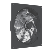
5
‘• Do not use metal compression-gland ttings with plastic terminal boxes.
• Use a dummy plug seal for the compression-gland tting.
• When opening cable glands on the fan/motor, check the condition of the threaded connections and seals.
• Only use lines which can guarantee a permanent seal around the cable glands.
• Depending on the type pf cable gland, attach a water drain sleeve or use a sealing compound.
• Screw on plastic terminal box covers should be sealed with sealant.
• Starting torque for screw on covers, plastic version 1.3 Nm, metal version 2.6 Nm.
• Secure fan connection cable with cable fasteners or cable clips.
• Depending on the model the motors
- Can be equipped with PTC’s, internally connected thermal contacts, lead-out thermal contacts or without
thermal protection.
• Connect them as below:
- PTC on PTC triggering device
- Internally connected thermo-contact: no external connection feasible or necessary.
- Lead-out temperature monitors must be integrated in the control circuit in such a way that, if a fault occurs,
the motor cannot switch on again automatically after it has cooled down. The protection of several motors
using one protection device is possible by connecting the temperature monitors of the individual motors
in series. It must be remembered that if a temperature fault occurs at one motor, all motors will then be
switched o. In practice, motors are therefore assembled in groups so that emergency operation with
reduced performance is still possible if a motor fails.
- Without thermal protection: use a motor protection switch!
• When in fan motors for 1~230V +/-10% the mains voltage is permanently over 240V, in extreme cases the
temperature monitor can trigger. In such cases a capacitor-type with the next smaller capacity should be used
instead of the stated capacity.