7
6. START-UP
• Before rst-time start-up check the following:
- Installation and electrical connection have been properly completed?
- Electrical connection carried out in accordance with wiring diagram
- Turning diagram corresponds to turning direction arrow on fan housing. The airow direction or turning
direction determines the functionality of the fan, not the motor rotation eld.
- Is the protective earth connected?
- Connection data complies with the specications on the type plate.
- Motor operating capacitor data complies with the specication of the type plate (1 ph).
- Safety equipment is in place.
- Temperature monitor/motor protection switch are professionally connected and operating properly.
- All leftover installation materials and other foreign materials have been removed from the fan cavity.
- Cable gland is sealed.
- Do the installation position and the arrangement of the condensation drain holes in the motor corresponds
to each other (does not apply to protection class IP55 fans).
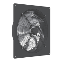
• The designated use of Woods Plate fans with VDE certication assumes connection in a device or via a control
unit.
• Start-up may only begin when all safety instructions have been veried and any hazards have been ruled out.
• Check for low vibration operation, strong vibration due to erratic operation (unbalanced), e.g. caused by
transportation damage or improper use, can lead to failure.
7. COMMUNICATIONS OPTIONS FOR EC FAN PROGRAMMING
Depending on the connection version and the auxiliary modules installed, there are dierent options for
communicating with the EC fan motor.
• With the ECBlue Basic connection version, the “AM-MODBUS-WB” auxiliary module provides an additional
option for programming using a mobile app.
• The MODBUS interface in the ECBlue BASIC-MODBUS connection version and the ECBlue Basic with AM-
MODBUS auxiliary module enables programming using the A-G-24NW hand-held terminal or a PC software.
For detailed information on installation and operation, please contact Woods Air Movement.