Operation 9
MAN1261 (4/11/2018)
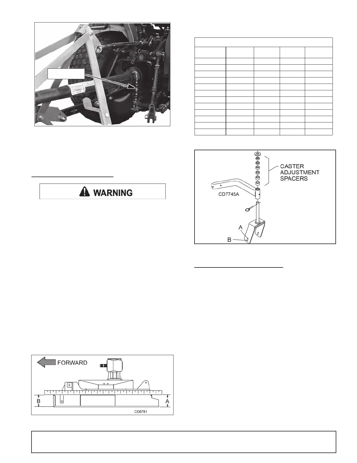
Figure 3
. Attaching Mower to Tractor
4.
Attach tether chain to tractor drawbar if drive equipped with chain, (Figure
3).
5.
Adjust the tractor lower 3-point arm anti-sway devices to prevent mower
from swinging side to side during transport.
CUTTING HEIGHT ADJUSTMENT
Keep all persons away from operator control area while performing
adjustments, service, or maintenance.
NOTICE
■
Avoid low cutting heights. Striking the ground with blades pro-
duces one of the most damaging shock loads a mower can encounter.
Allowing blades to contact ground repeatedly will cause damage to
mower and drive.
1.
Level mower from side to side. Check by measuring from mower frame to
the ground at each deck rail.
2.
Verify that the same amount of spacers are under all caster arms.
3.
Loosen cap screws that attach caster arm assembly to deck.
4.
Set mower on the ground.
5.
Retighten cap screws. This equalizes the clearance in the bolt holes.
6.
Adjust front of mower level with or slightly lower than the rear to obtain
best mowing results. See Figure 4.
7.
Control cutting height by adjusting front and rear caster wheels.
8.
To raise rear of mower, move caster adjustment spacers under rear
caster arms. See Figure 6.
9.
To raise front of mower, move spacers under front caster wheel arms.
Figure 4
. Cutting Height Adjustment
Remember, measurement at location A (Figure 4) should not be less than loca-
tion B and should not be over 13 mm greater than location B.
Figure 5
. Cutting Height Chart
Figure 6.
Height Adjustment with Caster Arm Spacer
s
TRACTOR TOP LINK ADJUSTMENT
When the cutting height is set, adjust tractor top link until mower top link attach-
ment point (A) is aligned vertically with mower hitch pin (B), Figure 7.
Adjust tractor top link so mower is level between caster wheel and ground
(dimension C), Figure 8. This will allow the mower to follow ground contour.
The mower has three lower hitch plate attachment points (D), Figure 7. It may
be necessary to change the mower hitch plate attachment point to obtain
proper tire clearance and/or lift height.
Cut Height Axle
Position
13 mm
Spacer
19 mm
Spacer
25 mm
Spacer
38 mm A
50 mm A1
64 mm A1
76 mm A1 1
89 mm A2
102 mm A1 2
114 mm A2 2
127 mm A22
140 mm A122
152 mm A222
165 mm B122
178 mm B222
Spacers under caster arm pivot tube