16 Operation
MAN0943 (11/1/2013)
Figure 2. Tractor Front Weight
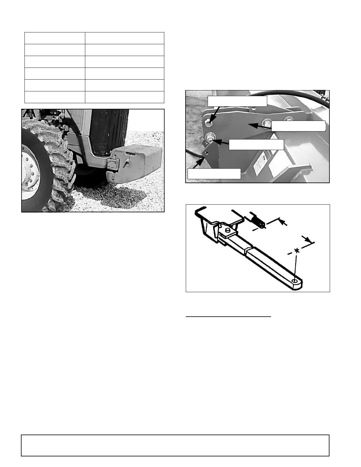
3. 3-Point Hitch
The 3-point hitch models require that the tractor be
equipped with a Category II or Category III 3-point
hitch. If the hitch can be converted from one to the
other, use a Category III to provide a wider stance and
more stability.
Use the upper top link hole for Category III and the
lower hole for Category II as shown in Figure 3.
For easier attachment, use a quick hitch. If not using a
quick hitch, use optional hitch extension.
4. Hydraulic Requirements when Using Center
Cutter Options
The tractor hydraulic system must be capable of 8 gpm
(30 lpm) at 1500 psi (10,335 kPa). The system cannot
exceed 28 gpm or 3000 psi. Either closed-centered or
open-centered systems can be used.
5. Load Sensing Hydraulics (3-Point Models Only)
Many newer tractors are equipped with “load sensing”
hydraulics. The operator is responsible for setting the
tractor hydraulic system to provide “float” on the 3-point
hitch. Refer to the tractor manual for specific instruc-
tions.
The “float” feature will allow the unit to follow the
ground contours during operation. This applies to 3-
point mounted machines only.
6. Drawbar (Pull-Type Models Only)
The tractor drawbar must be set to provide 20” (508
mm), between the end of the PTO shaft and the center
of the drawbar pin for 1-3/4 - 20, 1000 RPM drives. See
Figure 4. This dimension will provide the required
clearance for the CV (Constant Velocity) joint on the
front of the driveline.
NOTE: On Pull-Type models, do not cut driveline.
Figure 3. 3-Point Hitch Attachment
Figure 4. Drawbar Dimension
PTO DRIVELINE LENGTH
(3-Point & 2-point Models Only)
■
The unit is equipped with a PTO driveline long
enough to fit any tractor and 3-point linkage sys-
tem.
■
The operator is responsible for measuring the
dimensions of the driveline through its working
range. These dimensions will indicate if the drive-
line requires shorting to operate on the particular
tractor/unit attachment system. The operator must
check dimensions before using the unit for the first
time and each time a different tractor is used with
the unit.
■
Use the following procedure when determin-
ing driveline dimension:
Table 1: Tractor Horsepower (6-8) vs. Unit Width
Width Minimum Horsepower
20′ 120
22′ 132
25′ 150
27′ 162
30′ 180
Top Link Assembly
Upper Top Link Hole
Lower Top Link Pin
Lower 3-Point Pin
DP11