20 Operation
MAN0943 (11/1/2013)
NOTE: To avoid unnecessary wear on knives and
related parts, never set the unit lower than the recom-
mended setting. (See Balance Statement, page 5.)
SET OPERATING HEIGHT
Use stroke control spacers. The number and thickness
should be equal on each cylinder to keep shredder
level.
Figure 10. Setting Operating Height
On 3-Point models, be sure the floating mast is free to
slide in its mounting frame to allow the machine to fol-
low ground contours. Refer to Figure 11.
Figure 11. Free-Float Position
FLAIL KNIVES
The shredder is factory equipped with “L” or cup type
flails. The two types are interchangeable.
“L” Flails
“L” flails (Figure 13) work best when trash or crop resi-
due is standing.
Cup Flails
Cup flails (Figure 14) can pick up material from the
ground and work best in matted trash conditions.
The standard cup flail is 8-1/2 inches (216 mm) long
and is used for most applications. Optional 6-3/16 inch
and 7-1/2 inch (157 mm and 191 mm) flails are avail-
able to match the tip position to ground contour.
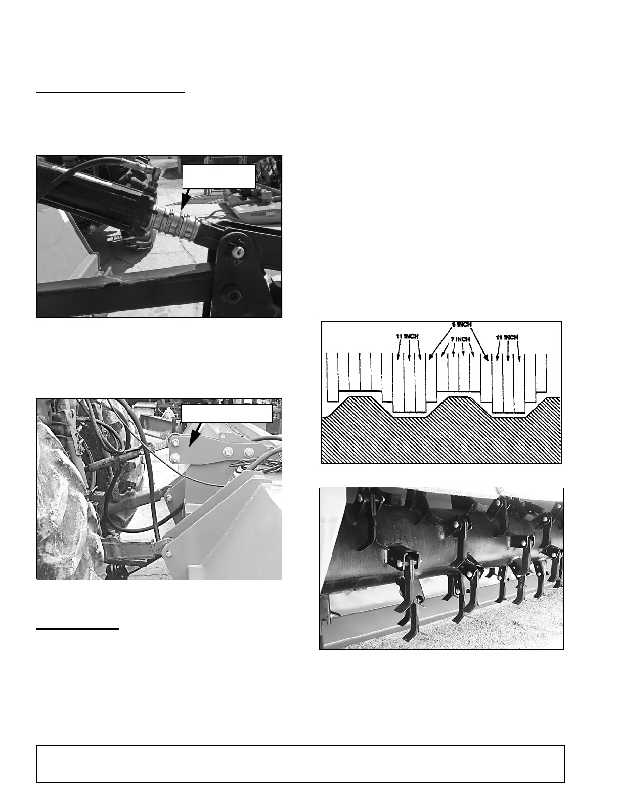
Attach optional cup flails as follows, making sure that
knives at 180° match (see Figure 12) (see Balance
Statement, page 5):
1. Leave standard flails located between the rows.
2. Remove others and install shorter flails to follow
ground contour. Be sure to mount the same size
flails on opposite sides of the tube. Measure the
row spacing and flail position carefully to minimize
ground contact. See page 38 and page 39.
.
Figure 12. Optional Flail Contour
Figure 13. “L” Flails
Stroke Control
Spacers
DP124