Do you have a question about the Woodward 2301E-ST and is the answer not in the manual?
Details safety alert symbols, LOTO, hazards, and required PPE.
Guidelines to prevent damage to static-sensitive electronic components.
Listings for CE Marking, Low Voltage Directive, ATEX, and EMC.
CSA certification for hazardous and ordinary locations.
Rules from American Bureau of Shipping, Bureau Veritas, CCS, DNV-GL, Lloyd's Register.
Compliance standards for Nippon Kaiji Kyokai, RINA, Australia/New Zealand.
Specific installation requirements for safe operation, including enclosure and wiring.
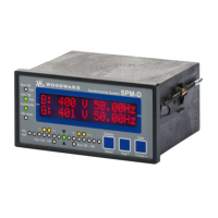
Overview of the 2301E-ST digital control for steam turbines.
Details the control's function for single-valve steam turbines and configuration options.
Lists related Woodward publications for additional product information.
Covers power requirements, environmental precautions, and location selection for the control.
Illustrates plant wiring for 2301E-ST, including diagrams and notes.
Details wiring practices, grounding, and EMI considerations for proper electrical connections.
Explains LED status, power supply, and transformer input connections.
Describes connections for load sharing lines, discrete inputs, and control logic contacts.
Details operation of start/unload, raise speed, and lower speed discrete input contacts.
Explains configuration and connection of contact inputs, actuator output, and analog inputs.
Details connection and configuration of speed sensors and programmable relay driver outputs.
Describes RS-232 and RS-422 serial communication ports for configuration and data transfer.
Outlines steps for visual inspection and checks before control start-up adjustments.
Explains the use of Control Assistant software for tuning and configuring the control.
Overview of the control's Configure menus for settings and adjustments.
Details parameters for speed, load, and start options configuration.
Explains configuration of discrete input functions for terminal inputs.
Details configuration of discrete output functions for relay drivers.
Explains configuration for analog input functions and types.
Details configuration of actuator output types and driver inversion.
Procedure for saving configuration changes and resetting the control.
Overview of the control's Service menus for monitoring and adjustments.
Displays real-time analog input and turbine status information.
Monitors generator load control status and related information.
Displays the status of various shutdown conditions and causes.
Shows current alarm conditions and identifies the first detected alarm.
Allows tuning of dynamic adjustments affecting turbine stability and transient performance.
Configures remote speed control logic via analog input or Modbus.
Sets up turbine speed set points, including idle, rated, and governor limits.
Enables control of system processes related to turbine speed or load.
Allows operators to test turbine overspeed protection logic and circuitry.
Configures logic for overriding MPU failure indications.
Sets up the synchronizer logic for generator synchronization.
Configures parameters for limiting actuator valve travel.
Sets up generator load control parameters and droop adjustments.
Linearizes the actuator/valve response curve for accurate control.
Guides the calibration of the actuator or valve travel.
Calibrates analog inputs and selects parameters for analog output.
Configures discrete output functions and level switch settings for relays.
Displays the status of discrete inputs and outputs for monitoring.
Tests analog and relay outputs by forcing signals.
Configures the serial port for Control Assistant and Toolkit communication.
Displays application software information, including part numbers and revisions.
Configures the serial port for Modbus communication.
Provides guidance for isolating control, actuator, or plant wiring problems.
Explains the boot code execution, status LEDs, and self-test diagnostics during power-up.
Outlines general checks, discrete input/output verification, and calibration procedures.
Addresses issues like no voltage, incorrect polarity, or faulty actuators preventing start.
Troubleshoots actuator response, linkage problems, and identifies shutdown causes.
Diagnoses speed sensor issues and control failures.
Addresses overspeed during starts, ramp rates, speed settings, and dynamic adjustments.
Troubleshoots overspeed at rated speed and control instability due to wiring or linkage.
Addresses problems with load sharing between units and maintaining constant speed in isochronous mode.
Introduces Modbus protocol, master/slave operation, and communication modes.
Defines Modbus message frame structure and supported function codes.
Details port settings and Modbus addresses for Boolean data.
Explains Modbus handling of analog data and control commands for shutdown/start.
Provides resources for detailed Modbus protocol information and registration.
Lists options for resolving installation or performance issues with Woodward products.
Outlines support from Original Equipment Manufacturers and Woodward Business Partners.
Factory options for product servicing including replacement, repair, and remanufacture.
Procedures and information required for returning equipment for repair.
Guidelines for safely packing controls for return shipping.
Information needed when contacting technical support for assistance.
| Actuator Type | Electric |
|---|---|
| Mounting | Panel mount |
| Control Function | Speed |
| Power Supply | 20–30 Vdc |
| Operating Temperature | -40°C to +70°C |