PRE-INSTALLATION
Greenstar i System Compact - 6 720 807 726 (2013/05)18
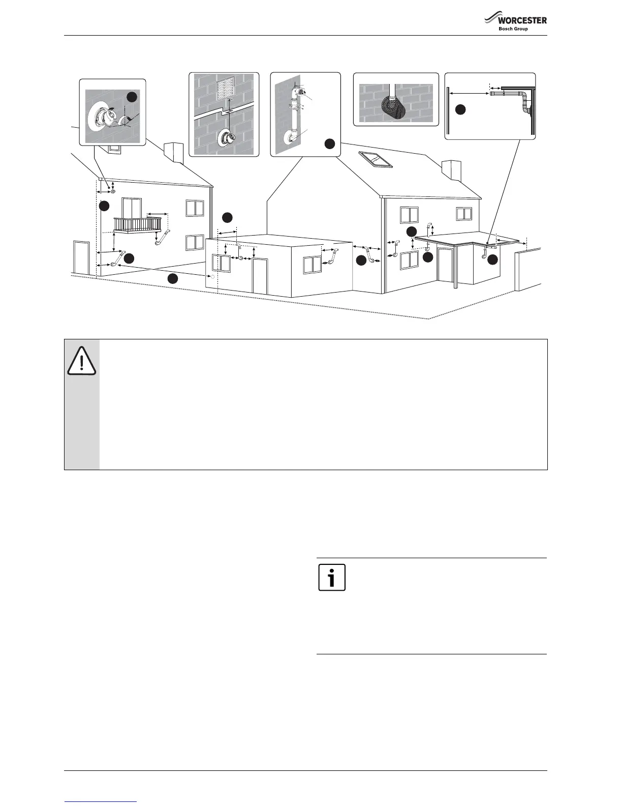
3.10 PLUME MANAGEMENT TERMINAL POSITIONS
Fig. 17 Plume terminal positions
Key to illustration
1.This feature allows some basic plume re-direction options on a
standard telescopic horizontal flue terminal.
300mm minimum clearances to a opening e.g. window.
However the minimum clearances to an opening in direction that the
plume management is facing, must be increased to 1,500mm. Where
the flue is less than 150mm to a drainpipe and plume re-direction is
used the deflector should not be directed towards the drainpipe.
2.300mm adjacent to a boundary line.
3. Plume Management Kit air intake can be reduced to 150mm providing
the flue exhaust outlet is no less than 300mm adjacent to a boundary
line.
4.1,200mm between terminals facing each other.
5.600mm distance to a boundary line, unless it will cause a nuisance.
BS 5440:Part 1 recommends that care is taken when siting terminal
in relation to boundary lines.
6.Using a Plume Management Kit the air intake measurement can be
reduced to 150mm providing the flue exhaust outlet has a 300mm
clearance.
Plume kits running horizontally must have a 10° fall back to the boiler
for proper disposal of condensate.
For details on specific lengths see relevant boiler Technical &
Specification information.
7.Internal/external corners. The air intake clearance can be reduced to
150mm providing the flue exhaust outlet has a 300mm clearance.
8. Clearances no less than 200mm from the lowest point of the balcony
or overhang.
9. 1,200mm from an opening in a car port on the same wall e.g. door or
window leading into the dwelling.
10.600mm distance to a surface facing a terminal, unless it will cause a
nuisance. BS 5440: Part 1 recommends that care is taken when siting
terminals in relation to surfaces facing a terminal.
NOTICE:
▶ All measurements are the minimum clearances required.
▶ The minimum length plume management length is 500mm to a maximum of 4,500mm, this includes two 90° bends.
Maximum flue length is reduced from 6,000mm to 5,000mm when plume management of 500mm is used.
Maximum flue length of 2,200mm with maximum plume management of 4,500mm
▶ For each metre (1000mm) of plume management length the internal flue length is reduced by 700mm.
▶ Subsequent 45° bends = 750mm and 90° = 1500mm.
▶ Refer to previous page for all concentric flue terminal positions unless the flue position is specified on the figure above “Plume
terminal positions”.
▶ Terminals must be positioned so to avoid combustion products entering the building.
▶ Support the flue at approximately one metre intervals and at a change of direction, use suitable brackets and fittings.
Note:
▶ Installations in car ports are not recommended.
▶ The flue cannot be lower than 1,000mm from the top
of a light well due to the build up of combustion
products.
▶ Dimensions from a flue terminal to a fanned air inlet to
be determined by the ventilation equipment
manufacturer.