OPERATION AND SERVICE INFORMATION
3-10
Read all of manual to become thoroughly familiar with this vehicle. Pay particular attention to all Notes, Cautions and Warnings
CHOKE
The choke is used to aid cold starting (Ref Fig. 10 on page 3-9).
See ‘Cold Starting’ (Refer to page 3-14) for instructions on using
the choke properly.
FUEL GAUGE
An electric fuel gauge is located to the right side of the key/light switch.
It indicates the amount of fuel in the tank (Ref Fig. 9 on page 3-9).
LOW OIL PRESSURE INDICATOR LIGHT
A low oil pressure indicator light is located on the dash panel (Ref Fig. 9
on page 3-9). If oil pressure drops below 1 - 4 psi (.1 - .2 kg/cm
2
), the oil
pressure switch will activate the light. Check oil level (Refer to page 3-
31). If oil level is between ADD and FULL mark on dipstick, a mechani-
cal problem exists within the engine and the vehicle must not be
driven. Contact a local Distributor or authorized Branch.
To prevent engine damage, do not
operate engine until oil pressure is
corrected. Do not overfill engine. Too much oil may
cause smoking or allow oil to enter the air filter
enclosure.
If oil level is below ADD mark on dipstick, add oil to bring level to FULL
mark (Refer to page 3-31). Drive vehicle a short distance and check oil
pressure. If oil pressure light does not come on, continue to use vehi-
cle.
ACCELERATOR PEDAL
Unintentional movement of
the accelerator pedal may
cause the vehicle to move which could result in
severe injury or death.
With the key switch ‘ON’, depressing the accelerator pedal starts the
engine and the vehicle begins to move in the direction selected. When
the pedal is released, the engine will stop (Ref Fig. 11 on page 3-10).
To stop the vehicle more quickly, depress the service brake.
SERVICE BRAKE PEDAL
Depressing the foot operated service brake pedal activates the
wheel brakes, slowing or stopping the vehicle (Ref Fig. 11 on page
3-10).
PARK BRAKE
The hand operated park brake is located on the console between the
front seats (Ref Fig. 10 on page 3-9). The brake is engaged when the
! !
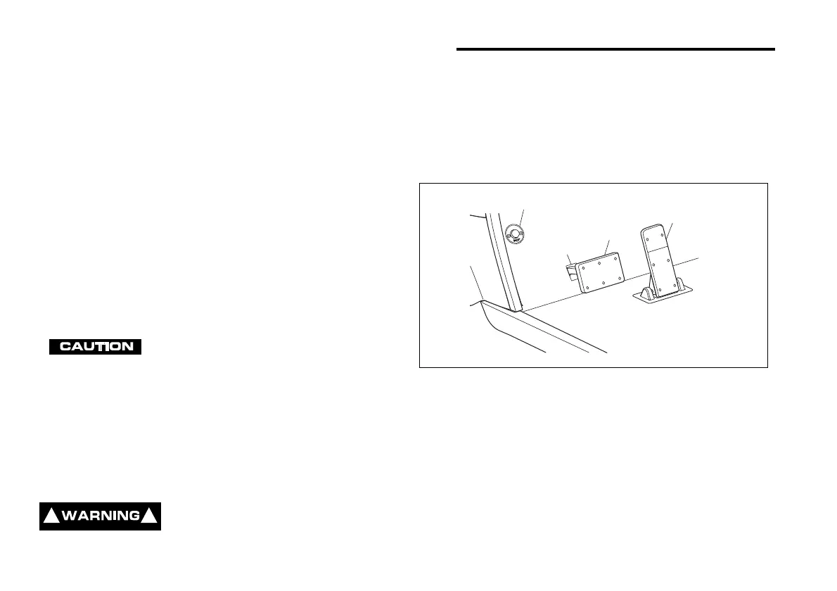
Fig. 11 Accelerator, Brake and Horn
Service
Brake
Accelerator
H
O
R
N
Horn
 Loading...