CS200 Control Systems
32
Intallation & Set-up
The CS200 CONTROL SYSTEM consists of the following components:
• Main Control
• VFD Display Module
• Wiring Harness Assembly
• Power Supply
• Thermocouple Assembly
• Lid Switch Assembly
• Sensor Assembly
• Cryogenic Solenoid Valve
• Remote Alarm Plug
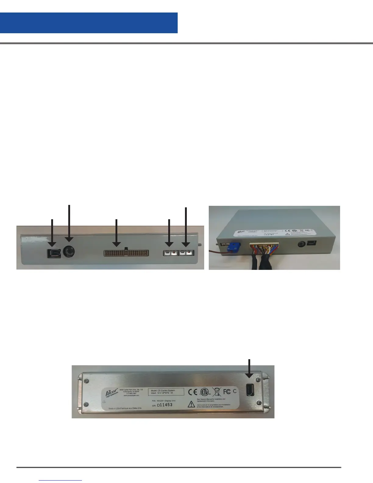
Connect the wiring harness assembly to the main control. The connector is keyed and can only be plugged in
one way.
Connect the thermocouple plug of the harness assembly into the control at the thermocouple plug labeled
T/C #1. One of the blades on the plug is slightly wider insuring that it is plugged in correctly. The copper blade
should plug into copper-colored plug. Finally, connect the display cable into the main control and the display.
Figure 9.0 Main Control Back Panel
Figure 10.0 Connection to Main Control
Controller Operation
Display
Connector
Main Harness
Connector
T/C #1
T/C #2
Speaker
Connection to Main Control


 To Next Page