P. 8 / 12
Profibus DP – CBF-B1/CBFF-B1 Burner Control Box
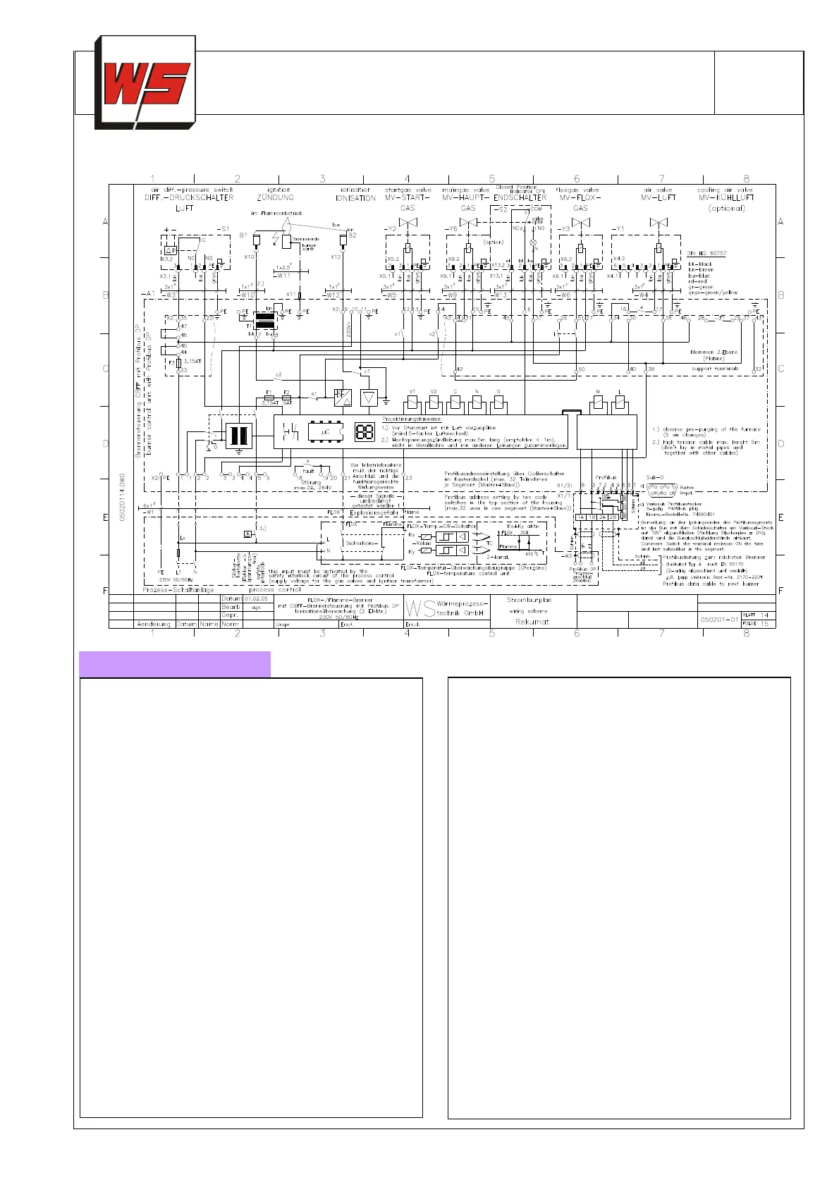
vor00161
Fig. 6: Connection diagram CBFF-B1 with Profibus
Power supply:
230V~, -15/+10% 50/60 Hz
115V~, -15/+10% 50/60 Hz (option)
grounded and ground-free grids
load: approx. 9 VA + valves and ignition trans
load
Control voltage for valves = Supply voltage
Current: max. 2 A per output
Total current for valves and ignition transform
2,5 A (load current on terminal X2.5)
Flame safety: Sensor voltage ca. 230V~, sensor cu
rent: > 1µA (UV or ionization)
Cable length: max. 5 m
Device fuses:
F1: 3,15A, slow, H, according IEC 127-2/5,
F2: 5 A, slow, H, according IEC 127-2/5 (F2 chang
able at WS only)
F3: 3,15A, H, slow IEC 127-2/5 for air valves (on ci
cuit board)
Fault outputs: max. 2 A, 264V AC, no in
(closed when fault)
Fault message also via Profibus DP
Input Flox, Flame, Air-Diff.-DS
115V~), load current per input approx. 3 mA
Max. switching cycles: 1.000.000
Ambient temperature: -
20 to + 60°C, dew formation
not permitted
Protection rating: IP 54 according EC 529
Weight: approx. 5 kg
Profibus-connection: via Variosub Profibus 9-pin
connector. Sub D (female)
(male counter connector avai-
lable as option)
Housing made of cast aluminum with removable flange
plate max. 2 cable grips M20x1,5mm for power supply.
Disengaging burner via Flame-FLOX activation signal
(burners with Flox function/CBFF-B1-control).
max. 2 cable grips (5 cables) M32x1,5mm for burner
connection, 4 threaded borings M6 in back panel for
mounting. Ground cable for burner is included (Cu blank
2,5 mm
2
)
Dimensions approx. 200x200x110mm (LxWxH)
Supervision cable: max. 5 m (High voltage cable)
Ignition cable: Recommended < 1m, max. 5m. ignition
load is reduced with increasing cable length. Do not run
in metal conduits, run separate of other cables. Use
shielded spark plug caps (1 kΩ resistor).
CBF-B1 burner control unit is in accordance with low vol-
tage guideline (73/23/EWG), EMV-Richtlinie
(89/336/EWG) and EN 298.
 Loading...