OPERATION MANUAL INSTRUCTIONS FOR HYDRAULIC PIPE
BENDING MACHINES
Construction
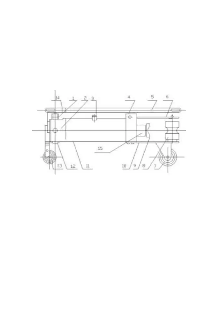
Fig. 1 shows its constructional appearance.
Fig. 1: structure figure
1- Ram Pump 2- Switch
3- Filler 4- Cylinder Seat
5- Handle 6- Upper Wing Board
7- Back Wheel 8- Supporting Wheel
9- Tube-Bending Mould 10- Lower Wing Board
11- Fuel Tank 12- Filter
13- Front Wheel 14- Handle Seat
15- Piston Rod