49@CgYdSXUc
DUSX^Ydb_^D" % GU \T3_^db_\
FUbcY_^F! !Q^TF! !1
'
'! "$$
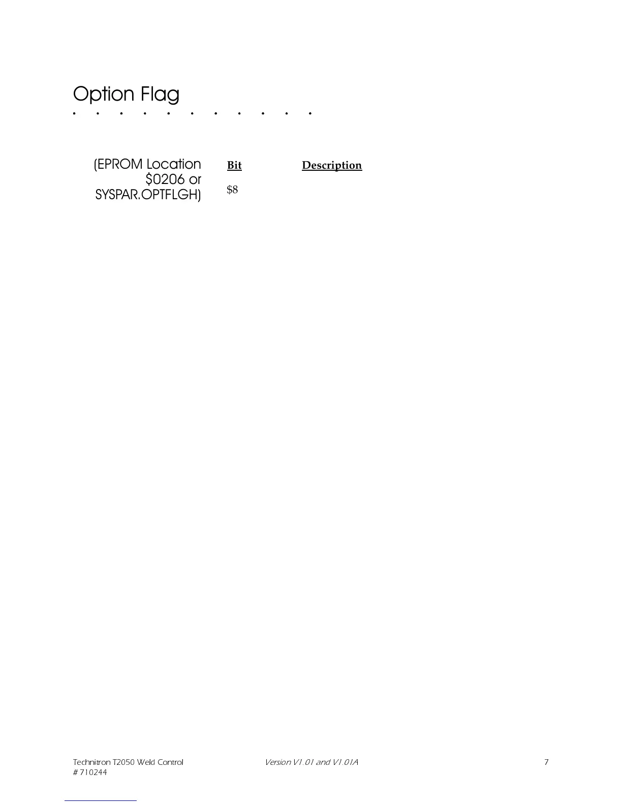
2SWLRQ)ODJ
(3520/RFDWLRQ
RU
6<63$5237)/*+
Bit Description
$80 (Reserved for future option)
$40 (Reserved for future option)
$20 (Reserved for future option)
$10 (Reserved for future option)
$08 Invert Fault Output:
(normal)>0 = Fault Output is ON when Fault is present
1 = Fault Output is OFF when Fault is present
$04 Valve s:
(normal)>0 = Normal 4-Bit Binary Valves
1 = Use 3-Bit Binary Valves, Valve4=Stepper End
Output
$02 Define SW3 operation:
(normal)>0 = SW3 OPEN = Use PS/SS Input for Second
Stage Input
SW3 CLOSED = USE PS/SS Input for Pressure
Switch
1 = SW3 OPEN = USE PS/SS Input for Second
Stage Input
SW3 CLOSED = USE PS/SS Input to Reset
Steppers
$01 Software Line Clock Filter:
0 = Disable Software Line Clock IIR Filter
(normal)>1 = Enable Software Line Clock IIR Filter
If you change a location listed above from (normal), you MUST
document your changes. At a MINIMUM, mark this manual
wherever necessary. Technitron recommends RoboNet download
control of SW1 and removing the switch from the board. With
SW1 removed, accidental changes cannot be made and the state
of the switches will be stored in the PC. If the features are
unknown and SW1 is removed, they may be uploaded from a
T2050 and thereby recorded in the PC.
SW1 is located on the right side of the upper edge of the T2050
Controller Board #824644 (see Figure 1 on page 2-4 and Figure 2
on page 3-5). Proper switch settings are CRITICAL to satisfactory
operation of the control. Be sure to study and understand these
functions thoroughly.
 Loading...