DXUDUSX^Ydb_^D" % 3_^db_\
" =_TYVYUT*'! ! ! DUSX^Ydb_^D" % GU \T3_^db_\
,QSXWVDQG2XWSXWV
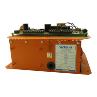
The control has seven inputs and six outputs. The functions
assigned to the I/O may be controlled by DIP switches or via
downloading from a personal computer through the RS-485
Network port TS1.
,QSXWV The inputs are
• FS1 – Initiate sequence 1 or Binary Pilot 1
• FS2 – Initiate sequence 2 or Binary Pilot 2
• FS3 – Initiate sequence 3 or Binary Pilot 4
• FS4 – Initiate sequence selected with the Data Entry Panel or
Binary Pilot 8
• ESTOP – Emergency stop
• WELD – External weld/no weld and
• PS/SS – (Second Stage or Pressure Switch) or (Second Stage
or Reset Steppers).
2XWSXWV The outputs are
• VALVE1 – Solenoid Valve 1 or Binary Output 1
• VALVE2 – Solenoid Valve 2 or Binary Output 2
• VALVE3 – Solenoid Valve 3 or Binary Output 4
• VALVE4 – Solenoid Valve 4 or Binary Output 8 or Stepper
end
• WCOMP – Weld Complete
• FAULT– Fault or Fault NOT
All solenoid valve outputs are protected by a pilot safety relay
(K7). K7 prevents possible unexpected gun closure due to failed
output modules. Relay K7 is "latched" in sequence by the output
of one of the valve outputs. Refer to the I/O hookup print at the
back of this manual.

 Loading...