DUSX^Ydb_^D" % GU \T3_^db_\
FUbcY_^F! !Q^TF! !1
#
'! "$$
7&RQWUROOHU%RDUG/D\RXW
0DMRU)HDWXUHVRIWKH&RQWUROOHU%RDUG
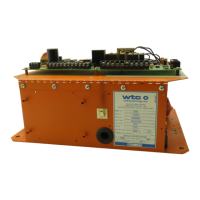
Figure 1 on page 2-4 illustrates the Controller board (p/n 824644)
used in the T2050 control.
Principal features to note are the following connectors, DIP
switches and hardware I/O points:
• TS1 – RS-485 Connections: Terminal strip TS1 has the
positive, negative and ground terminals required for
network communications using the RS-485 standard.
• TS2 – Control Inputs: Terminal strip TS2 is used to attach the
seven defined hardware user input points.
• TS3 – Control Outputs: Terminal strip TS3 includes the six
defined hardware user output points.
• TS4: Terminal strip TS4 has the terminals to accept the CT
(current transformer), toroid and OVERTEMP sensor inputs.
• Data Entry Panel Socket: This socket connects the power and
data transmit/receive signals necessary to operate the Data
Entry Panel (DEP).
• K7: This is the Pilot Safety Relay.
• P1 – KEY SW: This jumper is a substitute for an external key
switch.
• SW1: Switch 1 is eight DIP (dual in-line package) switches
used to configure features of the timer.

 Loading...