DIN-XP
Input module
with 16 operation or fault inputs
Page 4 of 4 Subject to technical changes DIN-XP_V2.7.0_PI_2019-04_EN
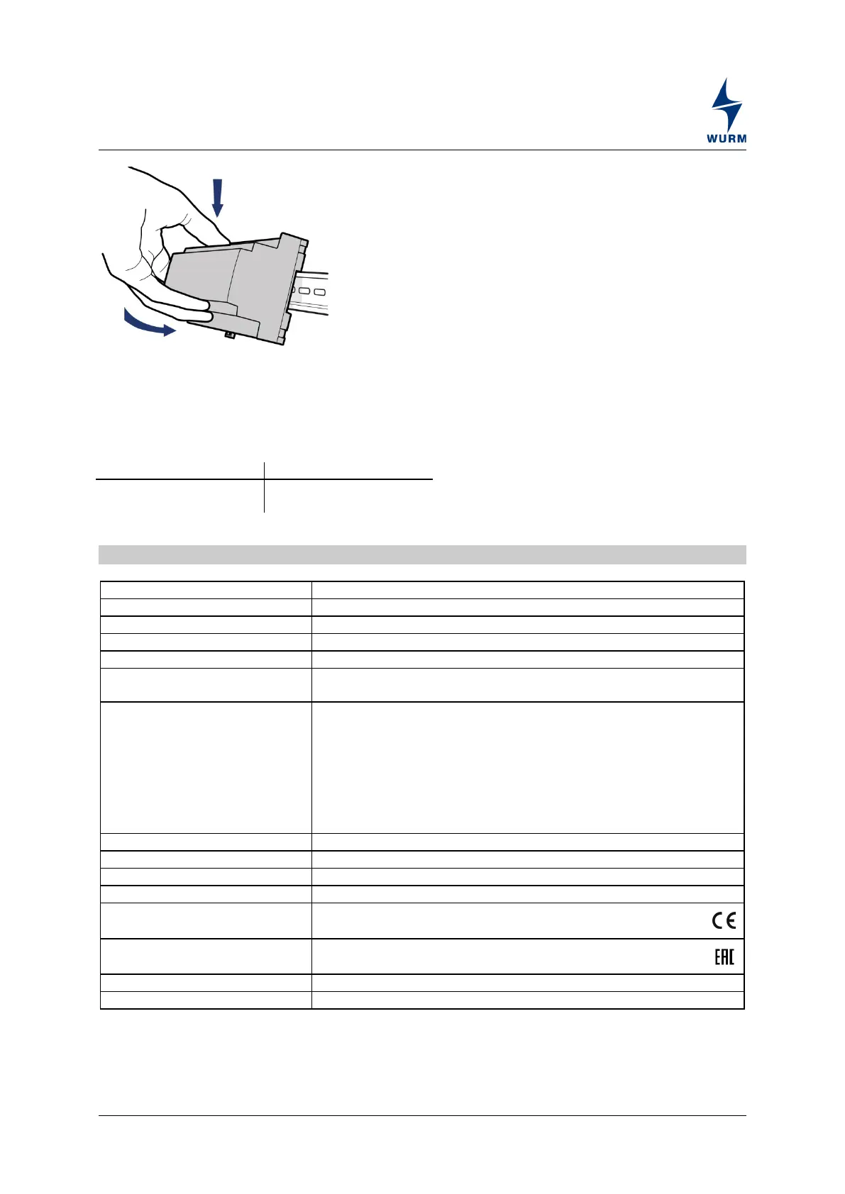
Place the device with the upper guide edge on
the top-hat rail.
Then press the device gently downward until it
engages with the fastening safety catch on the
top-hat rail.
For wiring of the data lines, we recommend the use of standard telephone lines 2x2x0.8ø. up to
lengths of 100m. The shielding must be grounded in the control cabinet. For cable lengths from 100m
to 400m, shielded lines with braided sheathing should be used.
We recommend the use of shielded cables for sensor extension.
Technical data
230V~, +10% / -15%, approx. 4VA
16 x for 230V~ (common neutral conductor)
2 x changeover contacts, 230V~, 4(2)A
Single-chip microcomputer, data memory
Self-monitoring of data memory and microcomputer
3-wire CAN bus interface with integrated power supply,
galvanically isolated, service socket
Gateway types
The device is supported by the gateways:
Multigate, from V1.0
CMD300, from V1.0
GTW-LAN 2.1
Global fault evaluation is supported by the gateways:
Multigate, from V2.4
CMD300, from V1.0
(WxHxD) 106 x 90 x 58mm (DIN 43880)
Top-hat rail TH 35-15 or TH 35-7.5 (DIN EN 60715)
Operation: 0...+55°C, storage: -25...+70°C
CE conformity
− 2014/30/EU (EMC Directive)
− 2014/35/EU (Low Voltage Directive)
EAC conformity
− TR CU 004/2011
− TR CU 020/2011
 Loading...