Do you have a question about the Würth Elmo Multi-Tester LED and is the answer not in the manual?
Important safety precautions and guidelines for operating the Elmo Multi-Tester LED safely and correctly.
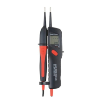
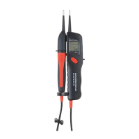
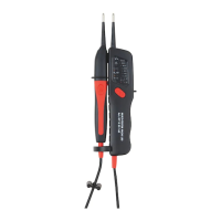
Description of the device's always-on activation and primary function.
Instructions for performing a self-test to verify the device's functionality and battery status.
Procedure and indicators for testing direct current voltages, including polarity detection.
Procedure and indicators for testing alternating current voltages, including polarity detection.
Method for identifying a live phase conductor using the device's LED indicator.
Procedure to determine the phase sequence (right- or left-handed) using two phase conductors.
How to test continuity and diode function, indicated by the Rx/Ω LED and acoustic signal.
Testing FI/RCD safety switches without triggering using automatic load, including L-N and L-PE tests.
Instructions for replacing the device's batteries, emphasizing correct polarity and disposal.
Specifications including display, voltage/frequency range, test current, continuity, protection, and approvals.
| Brand | Würth |
|---|---|
| Model | Elmo Multi-Tester LED |
| Category | Test Equipment |
| Language | English |