EasyManua.ls Logo

Wutong Electronic NWT4000-2 User Manual

Default Icon
75 pages
To Next Page IconTo Next Page
Page #1 background imageLoading...
Page #1 background image
1
NWT4000-2 RF DIGITAL
SWEEPER & ANALYZER
USER MANUAL
Manufacturer:
WUTONG ELECTRONIC
sitehttp://bg7tbl.taobao.com
TEL: +86134 2795 9750
Q Q: 1630 2767
Email: bg7tbl@126.com
version: V2.0
date: 2014-10-20
This document is based on the original manual from the supplier, edited
and updated by Kurt Poulsen (OZ7OU)
The document and applied editing and updates devoted entirely to
document the NWT4000-2 25MHz-4.4GHz unit (using 2xADF4351 PLL’s)but will
also be useful for the NWT4000-2 and NWT4000-1 series going from 138MHz to
4.4GHz (using 2xADF4350 PLL’s). However, the latest NWT4000-2 where the
SMD connector are on top of the PCB (and not at the edge) has improved
screening and far better dynamic range. Watch our when building it into a case
to use a plastic case. Using a metal case will most likely give elevated noise
floor by several dB in the GHz region.
Watch out that you do not purchase the version in a case with two SMA
connectors and a Green LED in between (believing it is a NWT4000 version), as
it most likely will only have 1 PLL (ADF4350 for 138MHz version and ADF4351
for 25MHz version) and thus only is a signal generator and spectrum analyzer,
not being able to sweep the frequency response of devices.
May 2015 edition

Table of Contents

Question and Answer IconNeed help?

Do you have a question about the Wutong Electronic NWT4000-2 and is the answer not in the manual?

Wutong Electronic NWT4000-2 Specifications

General IconGeneral
BrandWutong Electronic
ModelNWT4000-2
CategoryMeasuring Instruments
LanguageEnglish

Summary

Instrumental composition and technical characteristics

Installation and storage

The basic design

The hardware connection reference map

The software guide

Guides through installing the USB driver and WINNWT software.

Logarithmic Y scale sweep frequency settings

2.1 Select the sweep frequency mode

Describes how to choose the appropriate measurement mode for frequency sweeps.

2.2 Set the frequency parameter

Explains how to input start, stop, and step frequencies for scans.

2.3 Before starting measurement the Instrument should be calibrated

Emphasizes the importance of instrument calibration before taking measurements.

SWR

4.1 SWR Measurements

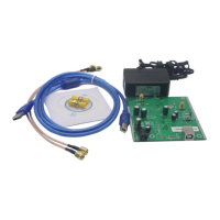
Explains how to enter SWR mode and the requirement for an external bridge.

4.3 SWR Calibration

Provides instructions for calibrating the SWR measurement setup.

Impedance - |Z|

6.1 Numerical Impedance measurements

Explains how to measure numerical impedance using a bridge and series resistor.

Measuring a device connection methods

7.5 An antenna measurement method

Explains how to measure antenna SWR using an external bridge.

7.7 Amplifier amplitude frequency characteristics measuring method

Guides on measuring amplifier frequency response, with connection tips.

Spectrum Analyzer

9.1 Spectrum Analyzer functionality

Explains how the NWT4000-2 acts as a spectrum analyzer using its PLLs.

Wattmeter

10.1 Wattmeter Functions

Describes the wattmeter's capability to measure frequency and suppress harmonics.

10.2 Wattmeter calibration

Provides steps for calibrating the wattmeter function for accurate readings.

The VFO mode

Frequency calibration

12.2 Enter VFO mode, output 1GHz/10MHz

Details entering VFO mode and outputting specific frequencies for calibration.

Appendix 4 NWT4000 Sweep flatness and frequency calibration

Appendix 4.2 Frequency calibration

Related product manuals