04. INSTALLATION
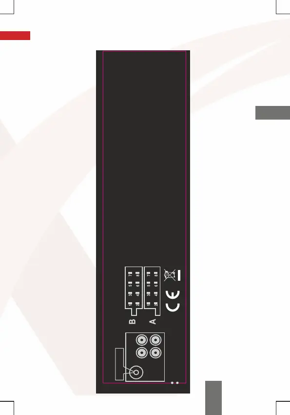
a. Diagram
A1: No connection
A2: No connection
A3: No connection
A4: Constant power from the
battery,+12V(Yellow)
A5: Car antenna-only, +12V (Blue)
A6: No connection
A7: Ignition switch, +12V(Red)
A8: Battery/chassis ground (Black)
POWER CONNECTION
Antenna input
White
Red
Left audio output(White)
Right radio output (Red)
CONNECTING 4 SPEAKERS
FM RADIO AND MP3 PLAYER
WIRING DIAGRAM
B/1. Right rear speaker output + (purple)
B/2. Right rear speaker output - (black-purple)
B/3. Right front speaker output + (gray)
B/4. Right front speaker output - (black-gray)
B/5. Left front speaker output + (white)
B/6. Left front speaker output - (black-white)
B/7. Left rear speaker output + (green)
B/8. Left rear speaker outpu - (black-green)
21
EN