7
Please run the main program for the programmer. If everything is set up correctly,
then the main screen should come up without any error message. At this point, you may
select a device and proceed with programming operation.
1.2.4 Communication Error Message
Communication error may occur if the PC failed to communicate with the
programmer. Please check the setup again and see to it that there is no device inserted in
the programmer socket.
Sometimes, the error message occurs when the programmer hardware is defective.
If the problem persists please contact factory for support.
.
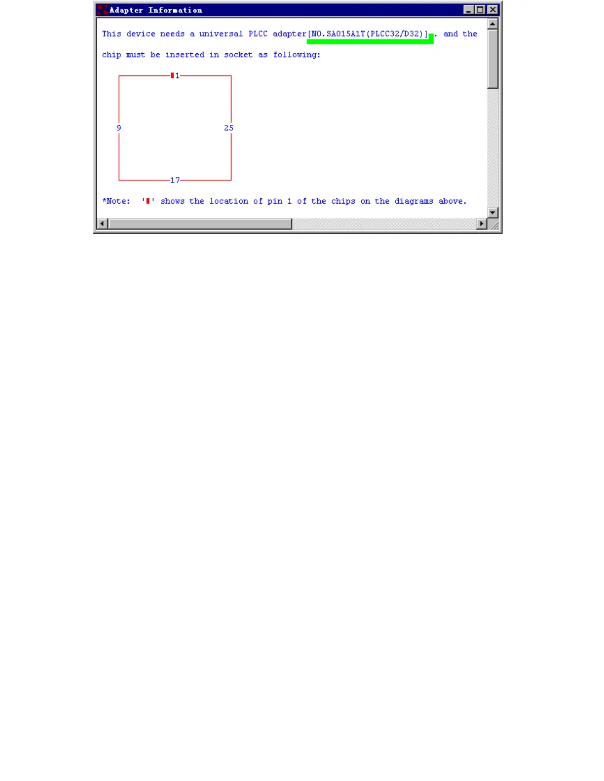
1.2.5 Device Insertion( example with PLCC32 )
For chips in DIP package
Follow the reference diagram next to the socket. Chips are always inserted at the
bottom line of the ZIF socket with the pin 1 facing toward upper left corner. For some
low-end models, some devices may need to be inserted in a non-standard way.
Instruction for insertion of such devices will appear on the screen when the
selection of the device is made.
For chips in None-DIP packages
Socket adapters are available for PLCC, QFP, TSOP, PSOP, SSOP, SOIC, SDIP,
BGA etc. packages. All adapters with 48 pins or less are constructed with top and
bottom pins connected 1 to 1.
1) Adapters with 48 pins or less on Superpro
Socket adapters are inserted in the same way as DIP packaged devices, which is at
the bottom of the 48 pins DIP ZIF socket. Chip insertion instruction onto the adapter is
displayed when the device is selected on the screen. Be sure to insert chips in correct
orientation.
Insert Device Figure