5
#33 M6*16 8PCS
10
45
#13 M8*16 4PCS
#12 d8*
20*2*R30 4PCS
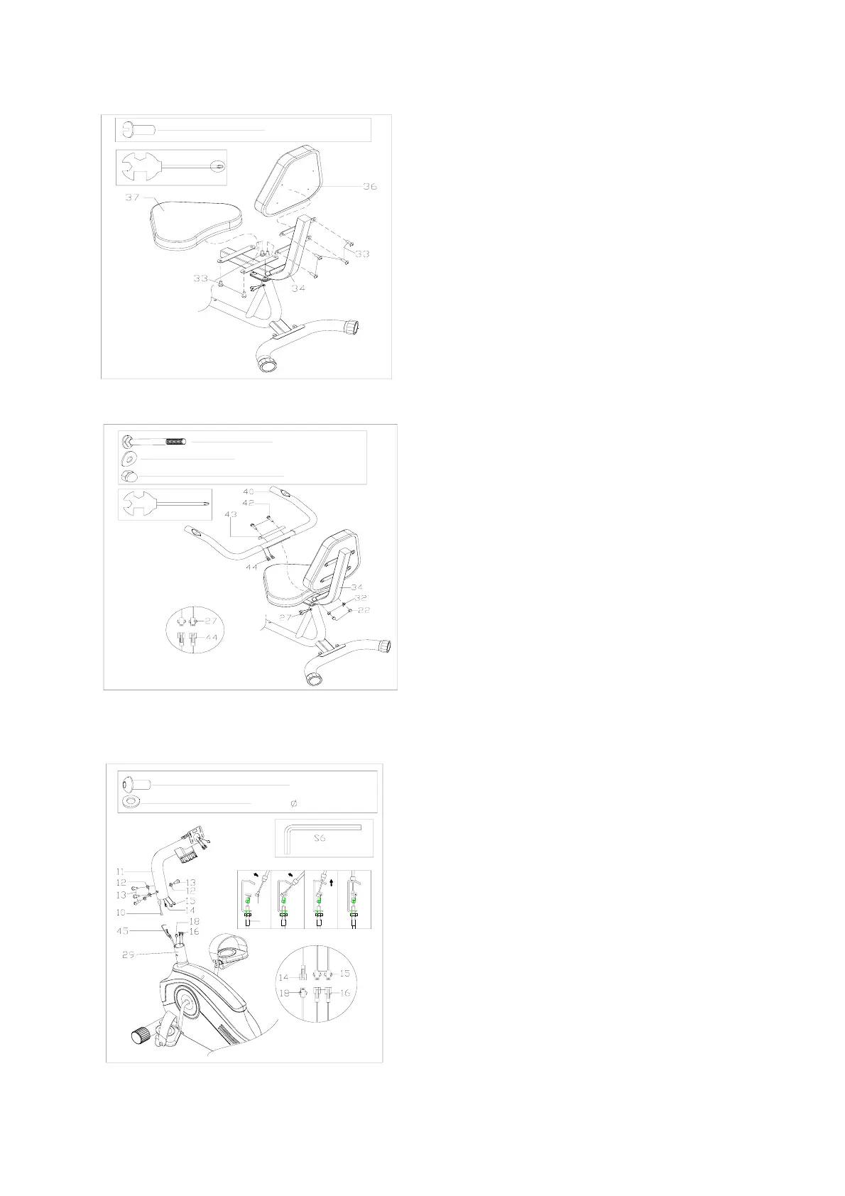
FIG.6:
Connect the sensor 14&18 and
tension control wire 10&45 as shown
in FIG.6, and install the support tube
(11) on the main frame (29) with arc
washer (12) and bolt (13).
FIG.4:
Attach the back cushion (36) and the
cushion (37) to the cushion post (35) with
the bolt (33).
S13
#42 M8*45 2PCS
#32 d8*Φ 16*1.5 2PCS
#22 M8 2PCS
FIG.5:
connect sensor line (27) with pulse wire
(44).Then,fix cover plate(43) and handlebar
(40) onto cushion post (34) with carriage bolt
(42), arc washer (32) and nut(22).