4
ASSEMBLY INSTRUCTION:
1.PREPARATION:
A. Before assembling make sure that you will have enough space around the item.
B. Use the present tooling for assembling.
C. Before assembling please check whether all needed parts are available (at the above of this
instruction sheet you will find an explosion drawing with all single parts (marked with numbers) which
this item consists of.
2.ASSEMBLY INSTRUCTION:
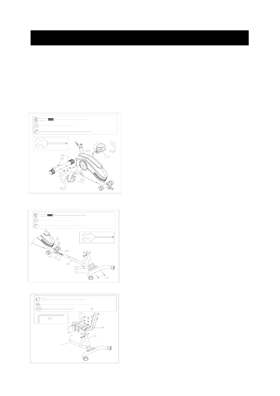
FIG.1
FIG.2: Attach the rear stabilizer (31) to
the back bracket (30) with carriage bolt
(21), domed nut (22) and arc washer(12).
Connect the sensor 16 & 27, and slide
the back bracket (30) to the main frame
(29), You will have to fixing the
Adjustment Knob (28).
#13 M8*16 4PCS
#7 d8 4PCS
#32 d8*
16*1.5 4PCS
FIG.1: Attach the front stabilizer (20) to
the main frame (29) with carriage bolt
(3), domed nut (22) and arc washer
(12).
Install left & right pedal (17L/R) to crank.
Then, lock the left pedal (17L) tightly in
counterclockwise direction. In addition,
lock the right pedal (17R) tightly in
clockwise direction.
#21 M8*62 2PCS
#12 d8*Φ20*2*R30 2PCS
#22 M8 2PCS
S13
S15
#21 M8*62 2PCS
#12 d8*Φ 20*2*R30 2PCS
#22 M8 2PCS
S13
FIG.3:
Attach the cushion post (34) to the back
bracket (30) with the nut (32) spring
washer (7) and bolt (33)