en - Original instructions
34
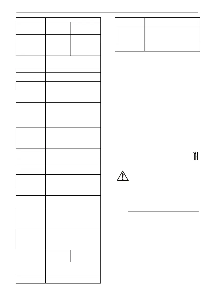
rent
1
12A 24A
Recommended
line protection
2
20A 40A
current
12 A 2 x 12 A
standby
(standby power may vary according
to the type of sensor connected)
Self-extinguishing - grey
55
Connections
(use copper
conductor only)
Screw terminal blocks
(power supply, input and output)
Maximum input
power cable
section
4 mm
2
Maximum motor
power cable
section
4 mm
2
Set point
3
Pressure: 0 to 60 bar (0 to 6
MegaPa)
Level: 0 to 50 m (0 to 164 feet)
Temperature: -20 to 100°C (32
0 to 40°C (32 to 122°F)
10 to 90% non-condensing
fuse F1, F2
CH10
Auxiliary protec-
tion fuse F3
1A Time-Lag 5 x20 mm
(T1L 250V IEC60127-2/3)
Digital inputs
5 multifunctional inputs for
NO/NC contact (voltage-free,
inputs
4 level electrode sensors,
1 reference electrode
Sensitivity: 5 to 100kOhm,
Line capacity: 10nF max,
Electrode voltage: 6.5V - 20Hz
Analogue input
(Sensor active value input)
Current input 0-22 mA, accuracy
0.3%,
Sensor power supply +12 Vdc
Digital outputs
1 Load relay 2 Load relays
Maximum current allowed for
the electric motor is 12A
TTL Serial port
Port for communication with the
supervision system via TTL with
ModBus communication protocol
Signals: +5V, RX, TX, RTS, 0V
RJ45 connector
Port RJ45 for communication with
the card with voltage-free relays
Signals: +12V - 120mA , 0V,
See Figure 3
1. The current supplied by the control panel shall
not be lower than the current absorbed by the
electric pumps, and depends also on the volt-
age drop due to the length of the cable.
2. Choose the current of the line protection de-
vice in relation to the maximum current ab-
sorbed by the motors.
3. Only if the electronic sensor is used.
4. For higher altitudes or other environmental
conditions not covered in this manual, please
contact your local After Sales / Service repre-
sentative.
3.4
Pump specifications
Refer to the user and maintenance manual of the
electric pump. It is essential to consider the limita-
tions of use of the control panel together with
those of the electric pump. See the
Technical data in
Tab 1. The customer is respon-
sible for checking the limitations of the electric
pump if they are not specified in this manual.
4 Installation
Precaution
• Observe the accident prevention
regulations in force.
• Use suitable equipment and protec-
tive devices.
• Always refer to the local regula-
tions, legislation and codes in force
regarding the selection of the instal-
lation site, plumbing and power
4.1
Electrical requirements
The local regulations in force overrule the specific
requirements given below.
Electrical connection checklist
Check that the following requirements are met:
• The electrical leads are protected against high
temperature, vibrations and collisions.
• The current type and voltage of the mains
connection must correspond to the specifica-
tions on the data plate on the pump.
• It is recommended to provide electrical power
to the control panel with a dedicated power
line equipped with:
 Loading...