7
0
2
0
4
1
0
3
0
0
2
0
4
1
0
3
0
0
2
0
4
1
0
3
0
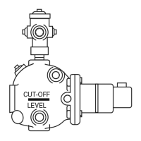
SCHEMATIC OF TWIN SWITCH
INTERNAL OPERATION
NORMAL WATER LEVEL
FEEDER OR ALARM
OPERATING LEVEL
LOW WATER CUT-OFF
OPERATING LEVEL
NEUTRAL WIRE
NEUTRAL WIRE
HOT WIRE
HOT WIRE
TO BURNER
TO ALARM
SAFETY
SWITCH
0
2
0
4
1
0
3
0
USED AS MAIN LINE SWITCH
Diagram 1 Diagram 2
NEUTRAL WIRE
TO
TWO WIRES OF 101A
OR TO ALARM CIRCUIT
HOT WIRE
TO BURNER
JUMPER
SAFETY
SWITCH
0
2
0
4
1
0
3
0
USED WITH MODEL 101 ELECTRIC
WATER VALVE OR IN ALARM CIRCUIT
Diagram 3
WIRING SCHEMATIC
SWITCH SCHEMATIC
IMPORTANT: Low water cut-off circuit of the 64 series must be electrically wired in series with all other boiler
limit operating controls.
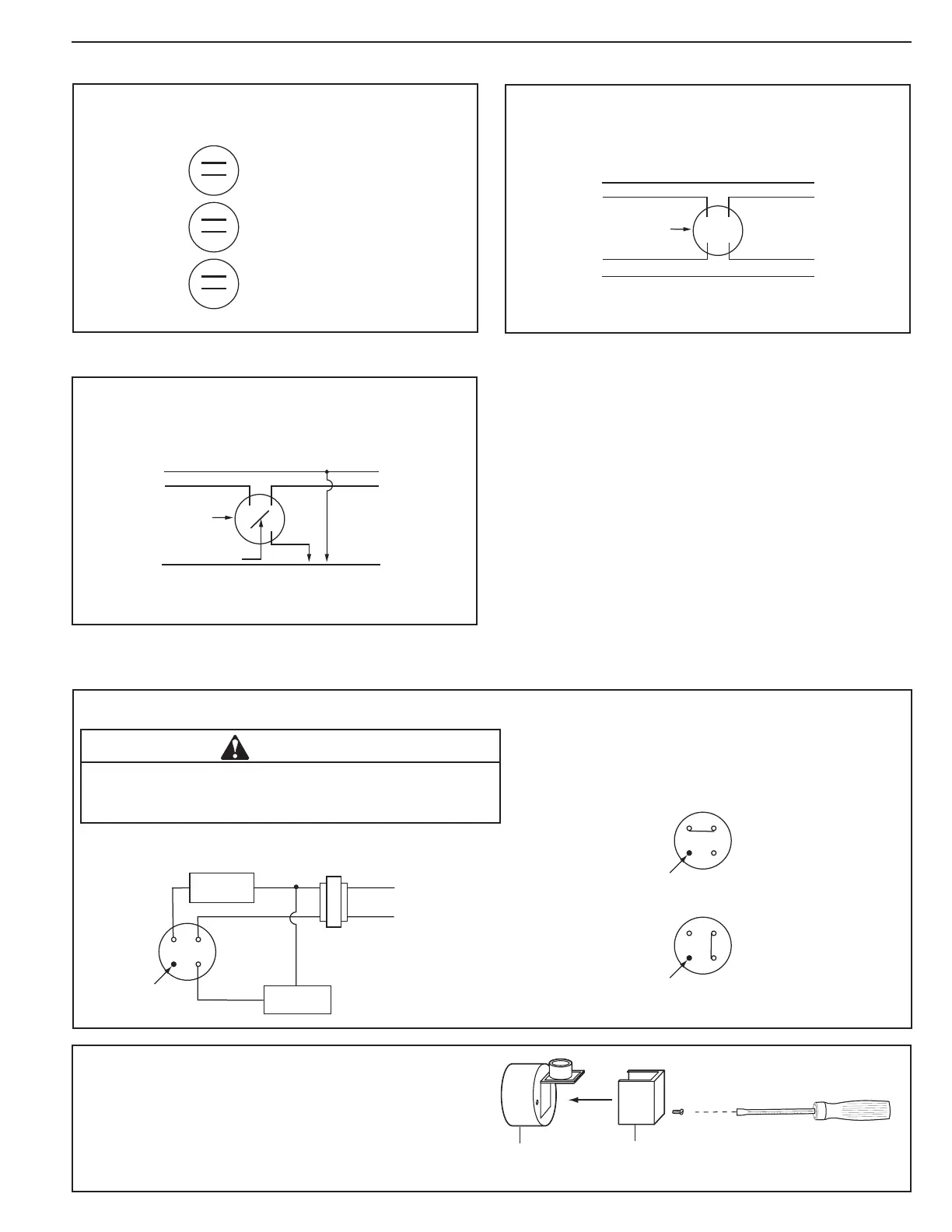
Place the cover on the switch housing and, using
a flathead screwdriver, tighten the one (1) screw
to approximately 2 ft•lb (2.6 N•m).
12
34
NEUTRAL
HOT
ALARM
RESET
BUTTON
BURNER
TRANSFORMER
(OPTIONAL)
Model 64A-M For use on 24 or 120 VAC systems requiring manual reset on low water cut-off.
Do not electrically connect water feeder to Model 64A-M. This
model includes a manual reset feature, failure to follow this
caution could result in boiler flooding and property damage.
CAUTION
NORMAL WATER LEVEL
12
34
RESET
BUTTON
12
34
RESET
BUTTON
LOW WATER CUT-OFF
ALARM LEVEL
 Loading...