This document is an instruction manual for a Rule Float Switch, a device designed for use in marine environments to control pumps, typically bilge pumps. The manual provides essential information regarding its function, installation, safety precautions, and technical specifications.
Function Description
The Rule Float Switch is an automatic switch that senses water levels and activates or deactivates a connected pump. It is designed to turn a pump ON when the water level reaches a certain height and turn it OFF when the water level drops. This automation helps prevent flooding in boats or other applications where water accumulation needs to be managed. The switch can operate in an "AUTO" mode, where it automatically controls the pump based on water levels, or a "MAN" (manual) mode, allowing for continuous pump operation regardless of water level. There is also an "OFF" position to completely disable the pump.
Important Technical Specifications
The manual provides a table detailing different models and their specifications, including voltage, wire size, wire length, maximum amps, and warranty.
- Voltage: The float switches are designed to operate with DC power systems, specifically 12V, 24V, and 32V.
- Model 35A: 12/24VDC
- Model 37A: 12/24/32VDC
- Model 40A: 12/24/32VDC
- Wire Size:
- Model 35A: 16 Gauge (1.29mm)
- Models 37A and 40A: 14 Gauge (1.63mm)
- Wire Length: All listed models (35A, 37A, 40A) have a wire length of 28 inches (712mm).
- Max. Amps:
- Model 35A: 14A (12V) / 7A (24V)
- Models 37A and 40A: 20A (12V) / 10A (24V) / 6.5A (32V)
- Guard:
- Models 35A and 37A: No guard
- Model 40A: Yes, includes a guard.
- Warranty (years):
- Models 35A and 40A: 2 years
- Model 37A: 5 years
- Activation/Deactivation Levels: The switch turns ON when the water level reaches 2 inches (5.1cm) and turns OFF when the water level drops to 3/4 inch (2cm).
- Operating Environment: This unit is designed for use with fresh water and salt water ONLY. It is explicitly stated that using it with any other hazardous, caustic, or corrosive material could result in damage to the pump and the surrounding environment, as well as possible exposure to hazardous substances and injury.
- Fuse Requirement: The manual emphasizes the importance of installing a proper fuse size to prevent damage to the product due to short circuits and to mitigate the risk of pump malfunction, personal injury, and fire hazard.
- CE Mark Compliance: When the product carries a CE mark, it conforms to various standards, including EN 61000-6-1:2001, EN 61000-6-3:2007 (Electromagnetic Compatibility Directive 2004/108/EC), ISO 8846 (Electrical Devices Protection Against Ignition of Surrounding Flammable Gases), and ISO 10133:2000 (Electrical Systems - Extra Low Voltage D.C. Installations Following the Provisions of the Recreation Craft Directive 94/25/EEC).
- ABYC Compliance: The product is designed to be installed to ABYC (American Boat and Yacht Council) standards, which set guidelines for safer boating.
Usage Features
The Rule Float Switch offers several features for effective and safe operation:
- Automatic Operation: The primary feature is its ability to automatically turn a pump on and off based on water levels, providing hands-free bilge management.
- Manual Override: A three-way switch (AUTO/OFF/MAN) allows users to manually activate the pump for continuous operation or turn it off completely, offering flexibility and control.
- Mounting Flexibility: The switch can be mounted directly to the bilge floor or to a flat surface using screws. The manual illustrates correct and incorrect mounting methods, emphasizing the importance of a stable, level installation.
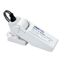
- Compact Design: The various models show different form factors, including a more compact, upright design and a flatter, elongated design, allowing for selection based on available space and specific installation requirements.
- Easy Installation: The manual includes diagrams for connecting the float switch to a pump and battery, indicating brown wire for power and black wire for ground. It also shows how the switch can be attached to a base.
- Tilt Tolerance: The switch can tolerate a maximum tilt of 5 degrees from horizontal for its base and up to 30 degrees for the switch body itself, indicating some flexibility in installation angles while maintaining functionality.
Maintenance Features
While the manual doesn't explicitly detail "maintenance features" in the traditional sense, it provides critical installation and operational guidelines that contribute to the longevity and proper functioning of the device, which can be considered preventative maintenance:
- Proper Mounting: The manual stresses the importance of mounting the switch correctly to ensure positive shut-off. It must be mounted equal to or above the pump base. Incorrect mounting (e.g., on an uneven surface or at an excessive angle) can lead to malfunction.
- Sealing Mounting Holes: All mounting holes must be sealed with a marine-grade sealant to prevent water intrusion, which is crucial for protecting the electrical components and the boat's structure.
- Wire Connection Protection: All wire connections must be kept above the highest water level. Wires should be joined with butt connectors and sealed with a marine-grade sealant to prevent wire corrosion, ensuring reliable electrical contact and preventing shorts.
- Fuse Installation: Always install the proper fuse size as specified in the technical table. This acts as a critical safety and protective measure against electrical overloads and short circuits, preventing damage to the switch, pump, and electrical system.
- Power Disconnection: Before working on the unit, it is a CAUTION to disconnect power from the system to avoid personal injury, damage to the surrounding environment, and damage to the unit itself. This is a fundamental safety practice for any electrical maintenance.
- Environmental Compatibility: The strict warning against using the switch with hazardous, caustic, or corrosive materials highlights a key "maintenance" aspect: ensuring the operating environment is compatible with the device's design to prevent premature failure and safety hazards.