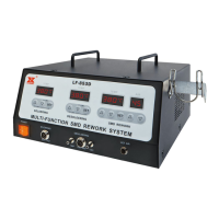
The Xytronic LF-8000 is a soldering/desoldering station designed for lead-free operations, offering a comprehensive solution for various soldering and desoldering equipment needs. It is suitable for hobbyists, service and repair technicians, and production personnel.
Function Description
The LF-8000 station provides both soldering and desoldering capabilities. It incorporates electronic circuitry that enables the user to fine-tune soldering tip temperature from 200°C (392°F) through 450°C (842°F) and desoldering tip temperature from 300°C (572°F) through 450°C (842°F). The unit features changing tips or heating elements for both soldering and desoldering irons. The desoldering iron is equipped with a precision wide nichrome heating element, offering 32V/100W output. An optional fume extraction kit can be equipped for soldering.
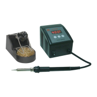
The station's temperature is maintained within +/-3°C (+/-6°F) of its operating temperature by a thermocouple sensor to ensure maximum temperature as close to the working surface of the tip as possible. This results in rapid heat-up, fast recovery, and exacting temperature control with minimal overshoot. The ergonomic and slender soldering iron design, with a comfortable silicone rubber grip, prevents operator fatigue.
The revolutionary "Zero Voltage" electronic switching design protects voltage and current sensitive components (CMOS devices, etc.) against damaging current and transient voltage spikes commonly produced by less efficient, mechanically switched stations. The power unit is isolated from the A.C. line by a transformer and allows 32Vac for soldering and desoldering to drive the heating elements. Both soldering and desoldering are constructed with an individual calibration port, located under the digital display on the face of the unit, for quick and convenient precision temperature adjustments.
Important Technical Specifications
LF-8000 Soldering/Desoldering Station:
- Power Supply: 120V/60Hz
- Soldering Iron: 32V/50W
- Desoldering Iron: 32V/100W
- Temperature Range (Soldering): 200°C (392°F) to 450°C (842°F)
- Temperature Range (Desoldering): 300°C (572°F) to 450°C (842°F)
- Temperature Stability: +/-3°C (+/-6°F)
- Heating Element: Nichrome
- Control System: Thermocouple sensor with "Zero Voltage" electronic switching
- RoHS Compliance: Designed for lead-free soldering/desoldering
SMD Tweezers (TWZ100):
- Operation Voltage: 32Vac
- Power Consumption: 100W (50Wx2)
- Temperature Range: 150-430°C (300-800°F)
- Standard Tip: 46-060102
- Suitable Components: Chip resistors, chip capacitors, SOT, flat pack ICs, small outlet 8-24 pins, flat package tunnel types, Dip ICs.
DIA80 Desoldering Iron:
- Operation Voltage: 32Vac
- Power Consumption: 80W
- Temperature Range: 300-450°C (572-842°F)
- Standard Tip: 44-915412-2075
Usage Features
Operating Procedures for LF-8000:
- Power On: Ensure the working voltage matches your power supply before beginning use. Check carefully for any damage during transportation.
- Unit Contains:
- DIA80: Desoldering iron assembly with tip.
- 210ESD: Soldering iron assembly with tip.
- Two iron holders with tip cleaners for both soldering and desoldering.
- AC Power cord with plug.
- Accessories include: one cleaning brush, one cooling strip, one 0.7 probe, and 4pcs of filters.
- Optional Parts:
- TWZ100: 32V/100W Tweezers can be interchangeable with 210ESD soldering iron.
- Fume extraction kit: For soldering iron only.
- HAP80: 32V/80W Hot air blow pencil can be interchangeable with DIA80.
Operating Procedures (General):
- Ensure the base unit's power switch is in the "OFF" position.
- Plug in "Solder and Desolder" wands, connect "Vacuum tube" to "VAC".
- Connect AC power cord to mains "In-Let".
Setting Temperature:
- Set "Temperature control knobs" to "MIN".
- Switch "Mains power switch" to "ON" position, then switch both "SOLDER & DESOLDER" switches to "ON" position. Both pilot lamps will be "ON".
- Tin the surface of both soldering and desoldering tips by applying a new covering of solder to protect it.
- Set both "Temperature control knobs" to the desired temperature about 3 minutes after being warmed. The unit will be ready for use once it reaches preset temperature – indicated by the pilot light going off.
- A slide switch below the digital display allows the operator to toggle between Fahrenheit and Celsius temperature readout.
- You can preset the temperature setting by pushing the slide switch to "SET" position. Use the temperature controlled knob to set the desired temperature. Then slide the switch to "READ". The temperature will then maintain a +/-3°C (+/-5°F) with the display showing actual tip temperature.
Desoldering Operation:
- Only activate the vacuum after the solder has completely melted. Melting is accomplished by moving the hot tip around the lead leaving visible melted solder on the component side of the P. C. B.
- Release the vacuum switch only after the solder on the tip has been removed, otherwise the tip may clog.
- Add solder to the joint of the component and allow the solder to melt completely for improved desoldering.
- Remove the solder collector and clean it after no more than 200 applications. However, daily cleaning is strongly recommended.
- Replace the cotton pad in the solder collector and the in-line filter when they begin to turn yellow.
- If there is insufficient vacuum, use the spring wire included to clean the tip and also check the in-line filters.
- Be sure that all filters are in place during operation or damage to the vacuum pump may occur.
Soldering Operation:
- Temperature above 410°C (770°F) should not be used for normal soldering purposes. However, irons can be used for short periods of time when occasion demands, but should be used with caution.
- See the OPERATING PROCEDURES section of this manual for tip replacement.
Maintenance Features
Care of Tips:
- The soldering, desoldering irons can reach very high temperature. Be sure to turn the unit off prior to carrying out any maintenance or trouble shooting steps listed below!
- Important: Remove and clean the tip daily. If a new tip is installed, remove any loose build up ion the tip and barrel assembly, otherwise the tip may fuse to the heating element or retaining barrel.
- Remove the tip and clean after each moderate to heavy use or daily for light usage. Remove any loose build up in the tip retaining assembly to prevent tip freezing.
- Both solder, desolder tips supplied are iron clad copper and if used properly should maintain optimum life.
- Always tin the tip before returning it to the station, turning off the station, or storing it for long periods of time. Wipe the tip on a wet sponge or our tip cleaner 460 prior to use.
- Keeping the iron set at high temperatures (more than 400°C or 750°F) will shorten tip life.
- Do not use excessive pressure on the tip or rub the joint with the tip while soldering and/or desoldering, it does not improve the heat transfer and may damage the tip.
- Never clean the tip with a file or abrasive materials.
- Do not use fluxes which contain chloride or acid. Use only rosin or resin activated fluxes.
- If an oxide film forms, it can be removed by careful buffing with 600-800 grit emery cloth, isopropyl alcohol or equivalent and then the tinned areas with rosin-core solder after the resin-core has melted.
Method to Check for Loss of Suction:
- The following procedures should be used on LF-8000 to check whether loss of suction is due to the tip, solder collector, tube or in-line filter.
- Caution: The desolder switch must be "OFF" and the iron allowed to cool before attempting the following procedures:
- Disconnect vacuum tube form the fitting on the front panel, place finger over the hole of the fitting, depress vacuum switch and you should have a strong vacuum. If not, send back to your nearest service center for pump repair.
- Disconnect the inline filter from the iron assembly, depress vacuum switch, replace filling of the in-line filter if there is little vacuum pressure or the filters are discolored.
- Remove solder collector from desolder iron assembly, place finger over the hole of the collector, depress vacuum switch. There is little suction clean or replace the collector tube.
- Depress vacuum witch, clean the tip tube with spring wire provided if there is no suction per the "Procedure for Cleaning Clogged Tip" section below.
Desolder Tip Replacement and Dressing:
- Desolder tips can be changed or replaced simply unscrewing the barrel nut assembly. The station must be turned off and allowed to cool before this operation.
- If the system Page 7 is left on without a tip in place, damage to the iron assembly may occur!
- After removing the tip, blow out any oxide dust that may have formed in the tip receptacle. Be careful not to get dust in your eyes. Replace the tip according to Figures 3-9 and hand tighten the securing screw for the barrel nut assembly. Pliers can be used to avoid contact with hot surfaces BUT SHOULD BE USED WITH CAUTION because over tightening may cause damage to the element or fuse the tip to the element.
Procedures for Cleaning Clogged Tips:
- Caution: This procedure is to be working in high temperature. Be careful to avoid burning your fingers during this operation.
- Be sure that the spring wire (included) will not go through the nozzle of the desolder tip.
- Adjust the heating element to a higher temperature allowing the clogged solder to melt. Clean the tip by sliding the spring wire up and down until the passage is clear.
- Unscrew the barrel nut assembly.
- Remove the tip using pliers.
- Insert the stainless tube of the tip back in the barrel to melt the solder.
- Remove again and shake out any loose melted solder in the tip. Replace the tip and screw back the retaining barrel nut assembly but care should be taken not to over tighten!
Procedures for Cleaning the Solder Collector:
- Caution: The desolder switch must be turned "OFF" and the iron allowed to cool before this operation.
- Hold iron as in Figure 10. Press and turn the red knob at the butt of the iron.
- Slide out the solder collector. (CAUTION: The solder collector is glass and thus retains heat, handle with care!)
- Point the collector down while shaking slightly and the waste solder will fall out. This task must be carried out periodically for proper operation of the station.
- Remove cooling strip with a pair of long nose pliers or tweezers.
- Clean the cooling strip and glass collector with wire brush (included).
Procedure for Replacing Filters:
- Be sure the iron/filter assembly have cooled.
- Hold iron as in Figure 10, press/turn red knob on the butt of iron.
- Remove solder collector.
- Disassemble the solder collector into 2 parts.
- Remove old cotton filter and replace.
Change of Cotton Filament (76-1411030):
- Please note that the cotton filament cannot be washed with the water. Water drops would be sucked into the Pump and may cause the pump damaged within 1 to 2 months. If you wash with the water. Cotton filament will turn solid and will stop the DIA60T working well. Please change at least once 3 to 5 days if you use 8 hours per day.
Change of Charcoal Filter (78-151500):
- Charcoal filter will turn solid if you wash with the water. If you use 8 hours per day that the Charcoal filter has to be changed within 3 weeks. On the other hand, if you wash the charcoal filter and do not dry properly, water drops will be sucked into the Pump and may cause the pump damaged easily.
Change of Glass Solder Collector (75-160110):
- Glass solder collector will be broken easily if the client knocked the DIA60T against the desktop. The glass collector also needs to be changed every 3 to 5 months usage.
Maintenance for Desoldering Heater and Tip:
- To prevent the desoldering tip being stuck by solder, the desoldering tip has to be cleaned by a Probe after every time usage. In such ways, desoldering tip's life can be lasting longer. Desolder Heater would be probably broken when you remove the desoldering tip with a pliers careless in hot condition. Slightly remove the tip with pliers or may use the anti-rusty cleaner when the tip clogged with the heater and do not forced open. Please read the "Procedure for Cleaning Clogged Tips" carefully on page 3 & 4 on the manual.