EasyManua.ls Logo

Yaesu ATAS-120A - User Manual

Yaesu ATAS-120A
1 page
Print Icon
Loading...
ACTIVE TUNING ANTENNA SYSTEM
ATAS-120A
I
NSTALLATION/OPERATING INSTRUCTIONS
The is a unique mobile antenna designed for use with Yaesu the transceivers equipped for the ATAS system, such as the
FT-897, FT-847, FT-857 and FT-100/-100D. The
utilizes a motorized tuning system which resonates the radiating
element for lowest SWR without the need for expensive, inconvenient monoband resonating whip assemblies. The
is
designed to mount directly onto a standard mobile antenna mount (not supplied) which is compatible with its Type “M” (“m/m pitch
only”) base connector. Your Dealer will be pleased to help you select the ideal mobile mounting assembly for your vehicle.
Thank you for choosing exciting new
Active Tuning Antenna System. We hope and trust that you will enjoy many
years of enjoyable mobile operation with the
!
INSTALLATION
c
Inset the top whip element
through the hole in the wa-
terproof cap.
d
Insert the whip element into
the Antenna Coil assembly.
e
Slide the waterproof cap
down the element and on to
the Antenna Coil assembly.
f
Press the waterproof cap
snugly on top of the Antenna
Coil assembly, ensuring an
accurate fit to the contours of
the assembly.
g
Refer to the manufacturer’s
instructions, and install the mounting base assembly in a loca-
tion where a solid, secure ground connection to the car body
can be obtained.
Note: Installation of the on a hatchback or trunk
lid may not permit a low SWR to be obtained. A solid bond to
the car body is important so as to establish a counterpoise
for the vertical radiating element.
h
Connect the coaxial cable from the mounting base to the
transceiver’s HF antenna jack.
i
Refer to the transceivers operating manual, and set the
transceivers Menu selections associated with the ATAS
system.
For operation on the 144 and 430 MHz bands, in addition to
HF/50 MHz, you may wish to consider the purchase of a “Du-
plexer” (for the FT-857, FT-897 and FT-100/-100D) or
“Triplexer” (for the FT-847) device to connect to the appro-
priate transceivers antenna jacks; the Duplexer or Triplexer
will then automatically pass RF power from the band in use
while isolating the other two antenna jacks. If you do not have
a Diplexer or Triplexer, the coaxial cable connector from the
will have to be moved manually to the appropri-
ate antenna jack when you wish to operate on VHF or UHF.
OPERATION
See the “Operation” section of the transceivers operating
manual for details of
tuning and operation.
CAUTIONS
For mounting onto a trunk lid or hatchback of a vehicle,
utilize a mount which provides secure, strong mechanical
contact to the vehicle's frame (to support the antenna's
cross-sectional area while driving, as well as for ground-
ing purposes). Suitable mounts include the Diamond mod-
els TE5M and K400.
In the interest of operator safety, always use the minimum
transmitter power necessary to establish and maintain com-
munications while operating mobile, and restrict trans-
mitter operation when pedestrians are within one meter
(3.3 feet) of the radiating element.
Do not allow anyone to touch the radiating element dur-
ing a transmitting session, due to the danger of burning of
the skin caused by the high RF voltage present.
Do not install the
in a position where the
radiating element could come in contact with (A) any elec-
trical wiring, which could cause lethal shock, or (B) a
grounded metal surface, as this will disrupt communica-
tions and may cause arcing.
Do not touch the Antenna Coil Assembly of the
, so as to avoid undue stress to it or the mechanical
components within it.
Do not attempt to perform the tuning process while driv-
ing a vehicle.
Disconnect the
from the vehicle when wash-
ing your vehicle to prevent ingress of water into the
due to the high water pressure, or damage from the
brushes.
Because of the cross-sectional area of the
,
simple magnetic mounts will not provide sufficient hold-
ing power to secure the reliably, and are not
recommended.
The
is designed specifically for use with
Yaesu transceivers equipped for the “ATAS” system, and
is not capable of automatic operation with other trans-
ceiver models.
For base station operation, if you do not have a good coun-
terpoise system such as a townhouse balcony, VHF/UHF
performance can be enhanced by the installation of the
optional
Antenna Base Kit.
There are no user-serviceable parts inside this antenna.
Reckless turning of the top of the antenna coil may result
in breakage of the antenna coil wire and/or other internal
damage.
SPECIFICATIONS
FREQUENCY RANGE:
7
/14/21/28/50/144/430 MHz
Amateur Bands
H
EIGHT (Approx.): 1.4 ~ 1.6 meters (4.59 ~ 5.24 feet)
W
EIGHT (Approx.): 900 g (1.98 lbs.)
I
NPUT IMPEDANCE:50
M
AX. INPUT POWER: 120 Watts (A3J)
M
ATCHED SWR: Less than 2.0:1
(with proper counterpoise)
(Specifications subject to change without notice or obligation)
Element
Insert element
through hole in
Waterproof cap
Waterproof Cap
(supplied)
Antenna coil
assembly
Tighten Allen screw
to secure element
Allen wrench
(supplied)
VERTEX STANDARD CO., LTD.
4-8-8 Nakameguro, Meguro-Ku, Tokyo 153-8644, Japan
VERTEX STANDARD
US Headquarters
10900 Walker Street, Cypress, CA 90630, U.S.A.
YAESU EUROPE B.V.
P.O. Box 75525, 1118 ZN Schiphol, The Netherlands
YAESU UK LTD.
Unit 12, Sun Valley Business Park, Winnall Close
Winchester, Hampshire, SO23 0LB, U.K.
VERTEX STANDARD HK LTD.
Unit 5, 20/F., Seaview Centre, 139-141 Hoi Bun Road,
Kwun Tong, Kowloon, Hong Kong
VERTEX STANDARD
(
AUSTRALIA
)
PTY., LTD.
Normanby Business Park, Unit 14/45 Normanby Road
Notting Hill 3168, Victoria, Australia
EAC81X701
Question and Answer IconNeed help?

Do you have a question about the Yaesu ATAS-120A and is the answer not in the manual?

Overview

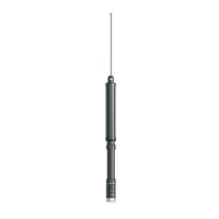
The ATAS-120A is an active tuning antenna system designed for mobile operation, specifically for use with Yaesu transceivers equipped with the ATAS system, such as the FT-897, FT-847, FT-857, and FT-100/-100D. Its primary function is to provide automatic tuning across various amateur bands, eliminating the need for multiple, expensive, or inconvenient monoband resonating whip assemblies. This is achieved through a motorized tuning system that actively resonates the radiating element to achieve the lowest possible Standing Wave Ratio (SWR).

Function Description

The core functionality of the ATAS-120A revolves around its ability to automatically adjust its radiating element. When connected to a compatible Yaesu transceiver, the antenna's internal motor system fine-tunes the antenna's length and electrical characteristics to match the operating frequency. This automatic tuning process ensures optimal performance and efficient power transfer from the transceiver to the antenna across the supported frequency ranges, which include HF, 50 MHz, 144 MHz, and 430 MHz amateur bands. The system is designed to simplify antenna operation for mobile users, allowing them to change bands without manually adjusting the antenna.

For operation on the 144 MHz and 430 MHz bands, users may consider purchasing a Duplexer (for FT-857, FT-897, and FT-100/-100D) or a Triplexer (for FT-847). These devices connect to the transceiver's appropriate antenna jacks and automatically route RF power from the active band while isolating the other two antenna jacks. Without a Duplexer or Triplexer, the coaxial cable from the ATAS-120A must be manually moved to the correct antenna jack when switching between VHF/UHF and other bands.

Usage Features

The ATAS-120A is designed for straightforward installation and operation. The installation process involves several steps:

  1. Inserting the top whip element through the hole in the waterproof cap.
  2. Inserting the whip element into the Antenna Coil assembly.
  3. Sliding the waterproof cap down the element and onto the Antenna Coil assembly.
  4. Pressing the waterproof cap snugly onto the Antenna Coil assembly to ensure a secure fit.
  5. Installing the mounting base assembly according to the manufacturer's instructions, ensuring a solid and secure ground connection to the car body. A crucial note here is that installation on a hatchback or trunk lid might not allow for a low SWR, as a strong bond to the car body is essential for establishing a proper counterpoise for the vertical radiating element.
  6. Connecting the coaxial cable from the mounting base to the transceiver's HF antenna jack.
  7. Configuring the transceiver's Menu selections to activate the ATAS system, as detailed in the transceiver's operating manual.

For mounting, it is strongly advised to use a mount that provides secure and strong mechanical contact to the vehicle's frame. This is important not only to support the antenna's cross-sectional area while driving but also for proper grounding. Suitable mounts include models like the Diamond TE5M and K400. Simple magnetic mounts are not recommended due to the ATAS-120A's cross-sectional area, as they may not provide sufficient holding power.

When operating, users should always employ the minimum transmitter power necessary for communications and restrict transmission when pedestrians are within one meter (3.3 feet) of the radiating element. It is critical to avoid touching the radiating element during transmission due to the high RF voltage present, which can cause burns. The ATAS-120A should not be installed where the radiating element could contact electrical wiring, which could cause lethal shock, or a grounded metal surface, as this could disrupt communications and cause arcing.

Furthermore, users should avoid touching the Antenna Coil Assembly to prevent undue stress or damage to its mechanical components. The tuning process should never be attempted while driving a vehicle. When washing the vehicle, the ATAS-120A should be disconnected to prevent water ingress due to high water pressure or damage from brushes.

The ATAS-120A is exclusively designed for automatic operation with Yaesu transceivers equipped with the "ATAS" system and is not compatible with other transceiver models for automatic tuning. For base station operation, if a good counterpoise system (like a townhouse balcony) is not available, VHF/UHF performance can be enhanced by installing the optional ATBK-100 Antenna Base Kit.

Maintenance Features

The ATAS-120A is designed with no user-serviceable parts inside. This means that users should not attempt to disassemble or repair the antenna themselves. Reckless turning of the top of the antenna coil can lead to breakage of the antenna coil wire or other internal damage, which would likely void any warranty and require professional service. The emphasis is on proper installation and careful handling to ensure the longevity and reliable performance of the device. Regular checks of the mounting integrity and coaxial cable connections are advisable to maintain optimal performance and safety.

Yaesu ATAS-120A Specifications

General IconGeneral
Impedance50 ohms
VSWRLess than 2:1
Tuning SpeedApprox. 5 seconds
Length1.2 m (extended)
Operating Temperature-10°C to +60°C

Related product manuals