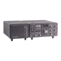
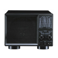
The YAESU Landliner Phone Patch/Speaker, model SP-901P, is designed to be used with the FT-901 series of all-mode HF transceivers. Its primary functions are to provide hybrid phone patch operation and to serve as an external speaker unit. The compact housing of the SP-901P is styled to match the FT-901 series, ensuring a cohesive appearance in a radio setup. All operating controls are conveniently located on the front panel, while necessary external connections are made via jacks on the rear panel.
Installation:
Installation of the SP-901P involves connecting the telephone line to the jack marked "LINE" on the rear panel. Other interconnections, such as those for the transceiver, are made as shown in the provided diagrams. The manual illustrates connections between the SP-901P and an FT-901 transceiver, showing a "PATCH" connection and a "LINE" connection, along with specific pin assignments for the connecting cables (PIN 6, PIN 1, PIN 2).
Front Panel Controls:
The front panel of the SP-901P features several controls for operation:
- PATCH Switch (1): This switch has two positions: "ON" and "OFF." In the "ON" position, the hybrid circuit is connected to the phone lines, and the transceiver is ready for phone patch operation. In this mode, the built-in speaker is disconnected. When the switch is in the "OFF" position, the phone patch is disconnected from the phone lines, and the built-in speaker is connected to the transceiver.
- RX GAIN Control (2): This potentiometer adjusts the amplitude of the received signal that is fed to the phone lines.
- TX GAIN Control (3): This potentiometer controls the amplitude of the phone signal that is fed to the microphone input of the transceiver.
- METER (4): The meter serves a dual purpose. During receive, it indicates the signal level fed to the phone lines from the transceiver. It is also used to measure the balance for the hybrid circuit, in conjunction with the MONITOR/NULL switch and the BALANCE control located on the rear panel.
Chassis Rear Apron Controls and Connections:
The rear panel of the SP-901P provides additional controls and jacks:
- MONITOR/NULL Switch (5): This switch is used during the balancing procedure of the hybrid circuit. It is placed in the "NULL" position for adjustment. For normal phone patch operation, it must be in the "MONITOR" position, where the meter indicates the signal level fed to the phone lines from the transceiver.
- BALANCE Control (6): This control is used to null the receiver audio output, which helps provide isolation between the receiver audio and the microphone input.
- TRANSMITTER HI-Z Jack (7): This jack is used to connect the patch output to the microphone input when the transceiver has a high microphone input impedance.
- LINE Jack (8): This jack is for connecting the telephone lines to the unit.
- RECEIVER 600 Ohm Jack (9): This jack is used with receivers that have a 600 ohm audio output impedance.
- LOW-Z IN Jack (10): This jack facilitates connections for the speaker output and the microphone input of the FT-901 transceiver.
Manual Phone Patch Operation:
To operate the phone patch manually:
- Place the PATCH switch in the "PATCH" position.
- Using a local telephone, contact the landline user and ask them to stand by.
- While receiving a signal, set the transceiver volume control to the 12 o'clock position. Adjust the RX GAIN control for a comfortable listening level through the telephone.
- Place the MONITOR/NULL switch in the "NULL" position and adjust the BALANCE control for a minimum signal level on the meter. The RX GAIN control should be set to approximately 3/4 clockwise rotation for this adjustment.
- Return the switch to the "MONITOR" position.
- Have the remote telephone user speak in a normal voice. Adjust the TX GAIN control so that the telephone line signal correctly modulates the transceiver when its MIC GAIN control is set to the 12 o'clock position.
- During manual phone patch operation, the station operator must monitor the conversation and manually switch the transceiver between transmit and receive using the PTT or MOX mode. Monitoring can be done through the telephone in the operating room.
Voice Controlled Operation (VOX):
If the telephone line signal quality is good, VOX operation can be performed. Proper VOX operation relies on achieving a good null of the receiver signal, as described in the manual phone patch section. The depth of this null is dependent on the quality of the telephone lines and is best when the line impedance is 600 ohms. If a good null is obtained, the telephone user should speak in a normal voice. Advance the FT-901 VOX GAIN control until the user's voice activates the transceiver VOX relay. The transceiver should revert to the receive condition when the user stops speaking. The FT-901 relay hold time control VR602 should be adjusted for smooth operation.
Internal Components and Specifications (from Parts List and Circuit Diagram):
The SP-901P incorporates various electronic components:
- Transformers: T1 (SA2-10936, #510002) and T2 (SA2-10937, #510003).
- P.C. Boards: PB-1667 (016670AZ and 60316670).
- Diodes: D1~4 (21090115, Ge 1N60).
- Meter: M1 (74000290, KTC-012 (VU)).
- Speaker: SP1 (76000010, SM-120, 4Ω 3W).
- Resistors:
- R2, 3, 5, 7 (42124331, Carbon Composition 1/2W GK 330Ω)
- R4, 6 (42124471, Carbon Composition 1/2W GK 470Ω)
- R1 (42124102, Carbon Composition 1/2W GK 1KΩ)
- R8 (42124103, Carbon Composition 1/2W GK 10KΩ)
- R9 (41143681, Carbon Film 1/4W TJ 680Ω)
- All resistors are 1/2W ±10% unless otherwise noted.
- Potentiometers:
- VR1 (49800080, RA25YQ20SB, 10ΩB/1KΩB)
- VR2 (49800107, CTM70A, 10KΩB/100KΩB)
- VR3 (49800106, EVC-BOAS-15B13, 1KΩB)
- Switches:
- S1 (62000004, MSB-6-2)
- S2 (63000010, SSF-22-08B)
- Capacitors:
- C2~5 (33824471, Dipped Mica, 50WV 470pF)
- C1 (38335105, Metalized Polyester Film, 250WV 1μF)
- All capacitors are in F (microfarads).
- Inductors: L1, 2 (53020002, FL7H222J, 2.2mH).
- Receptacles:
- J1, 2 (68020001, CN-7017J)
- J3 (68020010, SI-7501)
- J4 (68060010, D6-701-02)
- Accessories (Plugs):
- P1, 2 (67020001, CN-7017)
- P3 (67020009, SI-7502)
- P4 (67060006, E6-701-02)
The circuit diagram provides a detailed view of the internal connections and component placement, including the speaker, meter, transformers, potentiometers, switches, and various jacks. The notes on the circuit diagram specify that all resistors are 1/2W ±10% unless otherwise noted, all capacitors are in F (microfarads), and values are nominal.