29
©
2019 Columbus McKinnon Industrial Products GmbH
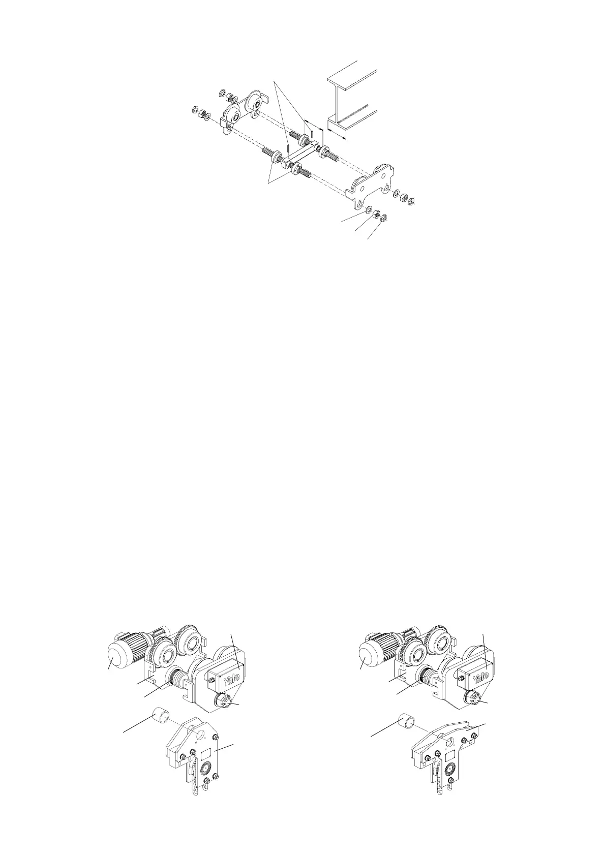
Assembly Of The Trolley 7,5 - 10t (see Fig. 11 and 12)
1. Measure the flange width of the beam .
2. Evenly distribute the spacer sleeves and spacer washers on both sides of the beam.
A clearance of 2 mm between the wheel flange and the beam flange must be maintained (inner dimension = flange width + 4 mm).
2. Evenly distribute the spacer sleeves and spacer washers on both sides of the load bar. The clearance between the trolley
wheel flange and the beam edge must be 2 mm on both sides when finally assembled.
Attention: When installing the load bar look out for the spacer for the supporting frame (Fig. 11 and 12).
3. Place the side plates on the load bar and distribute the remaining spacer washers on the outside of the side plates equally on both
sides ensuring that at least 1 large (3 mm thick) and 3 small adjusting washers (3 mm thick) are mounted between the side plate and
hexagon slotted nut. Secure one side plate with a hexagon slotted nut.
Tip: For easier mounting screw one side plate tightly. The other side plate is attached loosely. Pay attention to the desired position of
the drive side.
4. Then lift the entire unit to the beam and tighten all hexagon slotted nuts.
5. Secure all hexagon slotted nuts with cotter pins.
6. By traversing the trolley check the following:
• that a clearance of 2 mm is maintained on each side between the trolley wheel flanges and the beam outer edge.
• that the suspension traverse and consequently the unit is centred below the beam.
• that both hexagon slotted nuts are fitted and secured with cotter pins.
• that at least 1 large and 3 small adjusting washers are mounted between the side plate and hexagon slotted nut
• that the side plates are parallel.
• that all wheels roll freely and make good contact with the flange of the beam.
• that there are no obstacles on the driving surface.
noitpircseD .oN
1 Crossbar
2 Hex. nut
3 Washer
4 Centre traverse
5 Round nut
6 Side plate
7 Trolley wheel
8 Roll pin
9 Locknut
10 Roll pins
 Loading...