28
©
2019 Columbus McKinnon Industrial Products GmbH
Electric Chain Hoist With Trolley
The devices are delivered as pre-installed and are designed for the beam range A or B specified on the ratings plate. Before installing
the chain hoist, make sure that the width of the track beam is within the adjustment range of the delivered trolley (see Tab. 1).
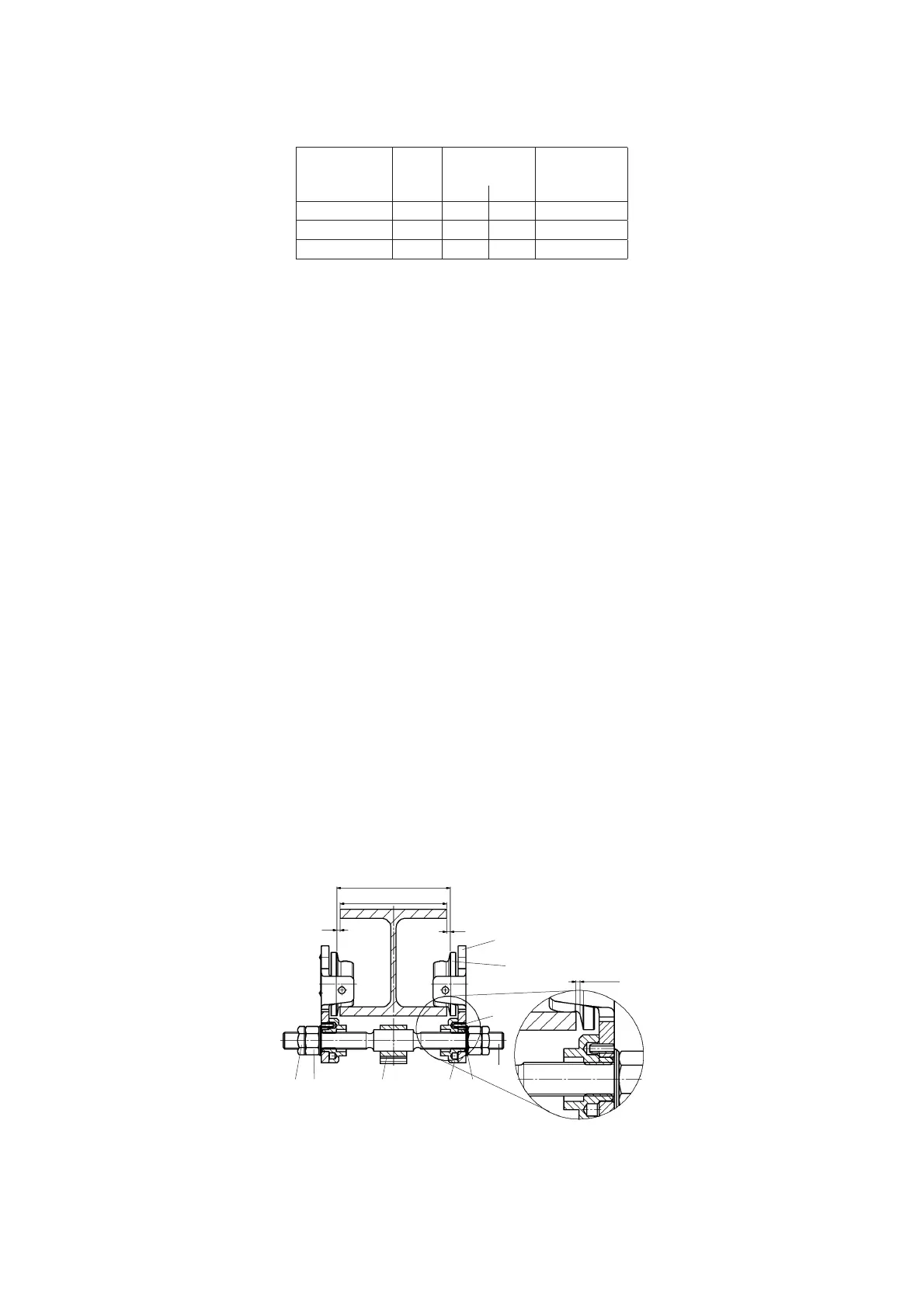
Assembly Of The Trolley 1,6 - 5t (see Fig. 10)
1. Unscrew the locking nuts (item 9) and hex nuts (item 2) from the crossbars (item 1) and remove both side plates (item 6) from the
trolley.
2. Measure the flange width of the beam (measure b).
Adjust measure B between the shoulders of the round nuts (item 5)
on the threaded crossbars (item 1). Ensure that the 4 bores in the round
nuts face towards the outside. Adjust the measure B to equal measure b
plus 4 mm. Measure A must be 2 mm on either side and the centre
traverse (item 4) must be centred between the round nuts.
4. Replace one side plate (item 6):
Replace one side plate ensuring that the roll pins (item 8) engage into
one of the 4 bores in the round nuts (item 5). To achieve this it may be necessary
to rotate the round nuts slightly.
5. Replace the washers (item 3) and tighten the hex nuts (item 2). Screw on the locknuts (item 9) finger-tight and tighten a further ¼ to
½ turn.
Attention: The locknuts must always be fitted.
6. Loosely replace the second side plate (item 6) on the crossbars (item 1). The washers (item 3), hex. nuts (item 2) and locknuts (item
9) can be fitted loosely.
7. Raise the complete pre-assembled trolley to the carrying beam.
ATTENTION: Pay attention to the position of the drive (optionally manual or electric)!
8. Engage the second side plate (item 6) ensuring that the roll pins (item 8) engage into one of the bores in the round nuts (item 5). To
achieve this it may be necessary to rotate the round nuts slightly.
9. Tighten the hex nuts (item 2) on the second side plate:
Tighten the locknuts (item 9) finger-tight and then a further ¼ to ½ turn.
Attention: The locknuts must always be fitted.
10. By traversing the trolley check the following:
• that a clearance of 2 mm is maintained on each side between the trolley wheel flanges and the beam outer edge.
• that the suspension traverse and consequently the unit is centred below the beam.
• that all 4 locknuts (item 9) are fitted .
• that the side plates are parallel.
• that all wheels roll freely and make good contact with the flange of the beam.
• that there are no obstacles on the driving surface.
Capacity
[kg]
Beam
range
Flange width
[mm]
Flange thickness
[mm]
min. max. max.
1.600 - 5.000 A 98 180 27
1.600 - 7.000 B 180 300 27
7.500 - 10.000 B 125 310 40
Tab. 1
 Loading...