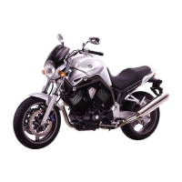
Do you have a question about the Yamaha 2005 BT1100 and is the answer not in the manual?
Explains how important information is distinguished in the manual.
Detailed technical specifications for the motorcycle model.
Maintenance specifications for the engine components.
Visual diagram illustrating engine lubrication points and flow.
Specifies torque values for various fasteners across different assemblies.
Lists lubrication points and symbols for engine and chassis components.
Diagrams showing lubrication flow paths for engine components.
Specifications related to the motorcycle's steering system.
Specifications for the front suspension components.
Specifications for the rear suspension components.
Specifications for the front brake system, including discs and pads.
Specifications for the rear brake system, including disc and pads.
Specifies the voltage for the motorcycle's electrical system.
Specifications for the ignition system, including T.C.I. and coils.
Specifications for the electric starter motor and relay.
Details on fuses used in the circuit breaker system.
Table detailing recommended periodic maintenance and lubrication intervals based on mileage.
Procedure for removing the engine from the motorcycle.
Procedure for removing the carburetors and associated components.
Procedure for removing the front brake master cylinder assembly.
Steps for disassembling the front brake master cylinder.
Procedure for removing the front brake calipers.
Steps for disassembling the front brake calipers.
Procedure for removing the motorcycle's handlebar and related parts.
Step-by-step guide for installing the motorcycle handlebar.
Procedure for removing the steering head lower bracket.
Identifies and illustrates key electrical components on the motorcycle.
Procedure for testing switch continuity using a pocket tester.
Instructions for checking various switches for damage, connections, and continuity.
Illustrates and describes different types of bulbs used on the motorcycle.
Procedure for checking the condition of motorcycle bulbs.
Procedure for checking the condition and continuity of bulb sockets.
Circuit diagram for the immobilizer system, showing component connections.
Explains the function and components of the immobilizer system.
Method for registering key codes to the immobilizer system.
Troubleshooting guide for immobilizer system failures.
Procedures for checking voltage at various points in the immobilizer system.
Explains the self-diagnosis device and error codes related to specific circuits.
Troubleshooting for throttle position sensor and speed sensor error codes.
Troubleshooting for speed sensor and wire harness issues.
Troubleshooting for ignition coil resistance and wiring.
Troubleshooting for fuel-cut solenoid circuits and wiring.
Circuit diagram for the motorcycle's ignition system.
Troubleshooting steps for ignition system failures (no spark).
Checks for ignition spark gap, spark plug cap, and ignition coil resistance.
Checks for pickup coil, main switch, engine stop, neutral, and sidestand switches.
Circuit diagram for the electric starting system.
Explains how the electric starting circuit operates under different conditions.
Troubleshooting guide for the electric starting system when the motor fails to turn.
Checks for starting circuit cut-off relay and starter relay continuity.
Checks main switch, engine stop, neutral, sidestand, clutch, start switches, and wiring.
Procedure for removing the starter motor and its assembly.
Steps for disassembling the starter motor components.
Procedure for checking the starter motor's commutator, diameter, and resistances.
Checking starter motor brush length, spring force, gear teeth, and oil seal.
Installing starter motor components during assembly.
Circuit diagram for the charging system, showing connections.
Troubleshooting guide for the charging system when the battery is not charging.
Checks stator coil resistance and charging system wiring.
Circuit diagram for the motorcycle's lighting system.
Troubleshooting guide for lighting system failures (lights not working).
Checks for pass switch, dimmer switch relay, igniter unit, and wiring issues.
Checks voltage for turn signal lights and neutral indicator light.
Checks tail/brake light and license plate light circuits.
Circuit diagram for the signaling system (turn signals, brake lights, horn).
Troubleshooting guide for signaling system failures and horn issues.
Checks horn switch, voltage, and wiring for the signaling system.
Checks tail/brake light and brake light switches.
Checks turn signal lights, flasher relay, and related wiring.
Checks turn signal switch, voltage for turn signals, and neutral indicator light.
Checks oil level warning light and oil level switch.
Circuit diagram for the fuel pump system.
Troubleshooting guide for the fuel pump system when it fails to operate.
Checks starting circuit cutoff relay, fuel pump resistance, and wiring.
Procedure for testing the fuel pump operation and ensuring it functions correctly.
Circuit diagram for the carburetor heater system.
Troubleshooting guide for the carburetor heater system when it fails to operate.
Checks the thermo switch and carburetor heater resistance.
Troubleshooting guide for engine starting failures or hard starting issues.
| Displacement | 1063 cc |
|---|---|
| Compression Ratio | 8.3:1 |
| Transmission | 5-speed |
| Final Drive | Shaft |
| Front Suspension | Telescopic fork |
| Rear Suspension | Swingarm |
| Front Tire | 120/70-ZR17 |
| Rear Tire | 170/60-ZR17 |
| Fuel Capacity | 20 liters |
| Engine Type | Air-cooled, 4-stroke, V-twin |
| Bore x Stroke | 95 x 75 mm |
| Ignition | TCI |
| Front Brakes | Dual disc |
| Rear Brakes | Single disc |


