1-4
UNCRATING PROCEDURE
(FOR TYPICAL STEEL FRAME)
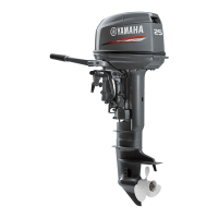
7. Remove the top cowling (6).
8. If the lifting points are covered by the fly-
wheel cover, remove it.
9. Attach a lifting harness (7) securely to the
lifting points (8), and tighten the harness.
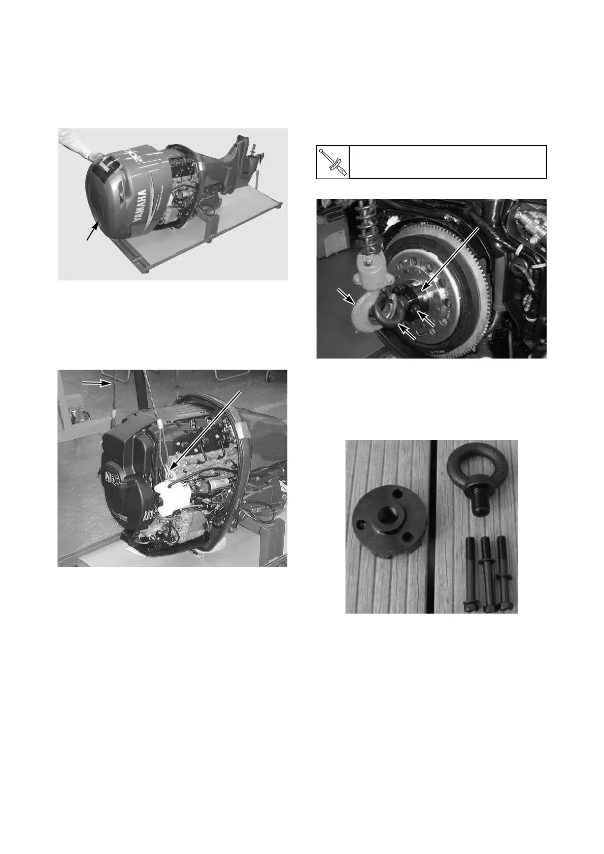
For 4-stroke V8, V6 (4.2L) and L4 (2.8L,
1.8L) engines, install the lifting attachment
(A) to the flywheel using the exclusive 3
bolts (B), insert the eye bolt (C) to the
attachment, attach a lifting harness (D) to
the eye bolt, and tension the harness.
* Special service tool for 4-stroke V8, V6 (4.2L)
and L4 (2.8L) engines: Lifting eye kit (P/N:
90890-06820)
Lifting eye kit contents:
To be continued.
M10 bolt (B) torque:
36 Nm, 3.6 kgf•m, 27 ft•lb
Eye bolt (C)Eye bolt (C)
Attachment (A)Attachment (A)
Eye bolt (C)
M10 bolt (B) M10 bolt (B)
90890-06821 (3 pcs)90890-06821 (3 pcs)
M10 bolt (B)
90890-06821 (3 pcs)
Attachment (A)
 Loading...