Do you have a question about the Yamaha GP1200 and is the answer not in the manual?
Explains how different models are indicated in the manual.
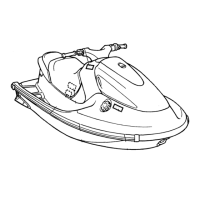
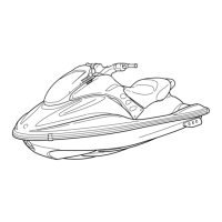
Explains that illustrations may differ between models.
Explains how references are used for page navigation.
Explains symbols related to chapter topics and general information.
Explains symbols indicating specific data points like torque and resistance.
Explains symbols related to lubricant types and application points.
Explains symbols for specific adhesives, sealants, and torque values.
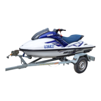
Details for identifying the specific watercraft model and serial numbers.
Essential safety precautions and practices for working on the watercraft.
Lists specialized tools required for maintenance and repair.
Procedures and charts for removing and installing components.
Provides overall technical specifications for the watercraft models.
Details specific measurements and tolerances for maintenance.
Specifies torque values for securing various components during assembly.
Outlines recommended maintenance intervals based on operating hours or time.
Procedures for inspecting and adjusting control system components like steering and cables.
Maintenance tasks for the fuel system, including filter and speed adjustments.
Procedures for inspecting and adjusting the oil injection system and carburetor.
Inspection and maintenance procedures for the power unit, focusing on spark plugs.
Inspection and maintenance of electrical components, particularly the battery.
Maintenance procedures for the jet pump, including impeller and strainer.
General maintenance checks and greasing points for various systems.
Exploded views and procedures for the fuel line system.
Exploded views and service points for the oil tank.
Procedures for removing the fuel tank assembly.
Steps for removing the carburetor unit from the engine.
Detailed procedures for removing individual carburetor components.
Exploded views and service points for the fuel pump assembly.
Exploded views and procedures for the oil line.
Exploded views and service points for the oil pump.
Procedures for removing the complete engine unit.
Exploded views and service points for the reed valve assembly.
Exploded views and procedures for the exhaust ring.
Procedures for removing the exhaust chamber.
Exploded views and procedures for the exhaust chamber.
Exploded views and procedures for the muffler assembly.
Exploded views and service points for the cylinder head.
Exploded views and service points for the cylinder.
Exploded views and service points for the piston and rings.
Exploded views and procedures for the flywheel magneto and base.
Exploded views and procedures for the electrical unit.
Exploded views and service points for the starter motor.
Exploded views and service points for the crankcase.
Exploded views and service points for the crankshaft.
Procedures for removing the intermediate housing.
Exploded views and service points for the intermediate housing.
Procedures for removing the entire jet pump unit.
Exploded views and procedures for the deflector and trim ring.
Exploded views and procedures for the nozzle, duct, and intake assembly.
Exploded views and service points for the impeller and drive shaft.
Exploded views and service points for the intake duct.
Exploded views and service points for cooling and bilge systems.
Exploded diagrams showing electrical component locations for GP760 and GP1200.
Exploded diagrams and procedures for the electrical unit.
Procedures for electrical system inspection and measurements.
Wiring diagrams, spark gap, and coil information for the ignition system.
Wiring diagram, battery, starter motor, fuse, and relay information.
Wiring diagram, fuse, battery, lighting coil, and rectifier regulator information.
Wiring diagrams and procedures for sensors, meters, and security functions.
Procedures for removing and installing handlebar components.
Exploded views and service points for the handle assembly.
Exploded views and service points for trim grip and control cables.
Exploded views and procedures for the engine hood cover.
Exploded views and service points for the handle column.
Procedures for removing adjustable mirrors and the engine hood.
Exploded views and procedures for the engine hood.
Exploded views and service points for the steering cable.
Exploded views and procedures for throttle and choke cables.
Exploded views and service points for the trim cable.
Exploded views and inspection points for seat, storage, and battery areas.
Exploded views and service points for the exhaust system.
Exploded views and service points for the deck area.
Exploded views and procedures for the gunwale.
Exploded views and installation procedures for mats.
Procedures for repairing hull damage, including scratching and punctures.
A comprehensive chart to diagnose common problems and check elements.
| Manufacturer | Yamaha |
|---|---|
| Model | GP1200 |
| Category | Boat |
| Type | Personal Watercraft |
| Fuel System | Carbureted |
| Seating Capacity | 2 |
| Starting System | Electric |
| Passenger Capacity | 2 |
| Engine Type | 2-stroke |
| Cooling System | Water |