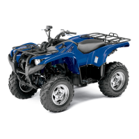
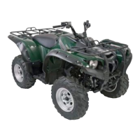
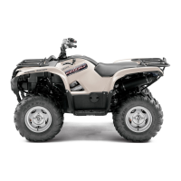
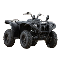
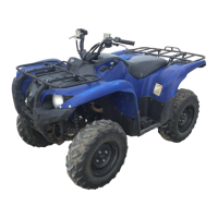
Do you have a question about the Yamaha Grizzly550 and is the answer not in the manual?
Details vehicle identification number and model label location for ordering parts.
Outlines the FI system, EPS system, and instrument functions.
Covers preparation for removal, replacement parts, gaskets, oil seals, and circlips.
Lists special tools required for tune-up and assembly, with part numbers.
Location of the stamped vehicle identification number on the frame.
Location of the model label for identifying the vehicle and ordering spare parts.
Explains the function and adoption of the Fuel Injection system.
Details the fuel pump, injector, and ECU control of the FI system.
Describes the components and function of the Electric Power Steering system.
Procedures for preparing the vehicle before disassembly, including cleaning and tool usage.
Guidance on using genuine Yamaha parts and recommended lubricants.
Instructions for replacing gaskets, oil seals, and O-rings during engine overhaul.
Procedure for replacing and using lock washers, plates, and cotter pins.
Information on the pocket tester tool and its part number for checking continuity.
List of special tools with part numbers, illustrations, and reference pages.
Provides overall dimensions, weight, and loading limits of the vehicle.
Details engine type, displacement, bore, stroke, compression ratio, and fluid capacities.
Covers frame type, suspension, wheels, tires, and brake specifications.
Lists voltage, ignition system details, ECU, sensors, and battery specifications.
Provides a chart for recommended maintenance jobs based on time intervals.
Details checks and adjustments for engine components like valves, spark plug, and oil.
Covers checks and adjustments for chassis components like brakes, tires, and steering.
Includes checks for battery, fuses, and headlight adjustment.
Procedures for removing and installing chassis components like skid plates and panels.
Covers removal, checking, and installation of front wheels and brake discs.
Details removal, checking, and installation of rear wheels and brake discs.
Procedures for checking and replacing front brake pads and master cylinder.
Procedure for removing the engine, including V-belt cooling ducts, muffler, and exhaust pipe.
Procedures for removing, checking, and installing the cylinder head and its components.
Procedures for removing, checking, and installing the cylinder and piston.
Details removal, checking, and installation of AC magneto and starter clutch components.
Covers removal, checking, and installation of the radiator and its components.
Details removal, checking, and installation of the thermostat and its housing.
Procedures for removing, disassembling, checking, and assembling the water pump.
Covers removal and installation of the fuel tank, fuel pump, and related hoses.
Details removal, checking, and installation of the throttle body assembly.
Procedure for checking fuel pressure using a pressure gauge and adapter.
Steps for adjusting the throttle position sensor angle using a digital circuit tester.
Lists possible causes and checks for engine starting failures.
Troubleshooting steps for incorrect engine idling speed.
Diagnoses common clutch problems, including vehicle not moving and clutch slip.
Identifies causes for poor braking performance.
Covers circuit diagram and troubleshooting for the ignition system.
Details circuit diagram and troubleshooting for the electric starting system.
Includes circuit diagram, ECU self-diagnostics, and troubleshooting for the fuel injection system.
Illustrates and lists various electrical components with their locations.
Schematic diagram of the ignition system wiring and components.
Guides on diagnosing and resolving ignition system failures.
Wiring diagram for the electric starting system.
Troubleshooting steps for starter motor failure.
Schematic diagram of the charging system.
Guides on diagnosing and resolving battery charging issues.
Wiring diagram for the vehicle's lighting system.
Troubleshooting steps for lighting system failures.
Schematic diagram of the signaling system.
Guides on diagnosing and resolving signaling system malfunctions.
Diagram of the cooling system's electrical components and connections.
Troubleshooting steps for radiator fan motor failures.
Wiring diagram for the fuel injection system.
Explains the ECU's self-diagnostic function and warning light indicators.
Table correlating fault codes with symptoms, causes, and troubleshooting steps.
Procedure for diagnosing engine malfunctions indicated by the trouble warning light.
Schematic diagram of the fuel pump system.
Troubleshooting steps for fuel pump failures.
Wiring diagram for the 2WD/4WD selection system.
Troubleshooting steps for the four-wheel-drive motor indicator light failure.
Wiring diagram for the Electric Power Steering system.
Explains the EPS control unit's self-diagnostic function and warning light.
Instructions for setting the diagnostic mode to identify EPS system faults.
Table correlating EPS fault codes with symptoms and probable causes.
Procedure for checking electrical switches for continuity using a pocket tester.
Instructions for checking bulb and socket condition and continuity.
Procedure for checking fuses for continuity and replacing blown fuses.
Guidelines for checking and charging the VRLA battery, including charging methods.
| Brand | Yamaha |
|---|---|
| Model | Grizzly550 |
| Category | Offroad Vehicle |
| Language | English |
