Do you have a question about the Yamaha MBK X-MAX 300 2017 and is the answer not in the manual?
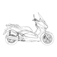
Details how to identify the vehicle and its components using VIN and model labels.
Describes the multi-function display and its various indicators and settings.
Lists essential special tools required for maintenance, including part numbers and reference pages.
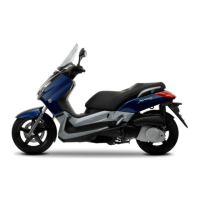
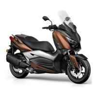
Provides overall dimensions, weight, loading capacity, and model details for the vehicle.
Lists detailed engine parameters, including displacement, bore/stroke, compression, and fluid capacities.
Details chassis components, including frame type, wheel/tire specifications, and suspension settings.
Outlines electrical system parameters, including voltage, ignition, battery, and bulb wattages.
Details recommended checks and adjustments for ensuring vehicle reliability and longevity.
Provides a chart of routine maintenance tasks based on odometer readings and annual checks.
Explains how to use the diagnostic tool to check for fault codes and perform dynamic inspections.
Provides step-by-step instructions for adjusting valve clearance on a cold engine.
Details the removal and installation of the battery cover assembly and windshield.
Covers the removal and installation of front cowling assemblies and related components.
Explains how to remove and install storage box and side covers.
Describes the procedures for removing, disassembling, checking, and installing the front wheel.
Covers procedures for checking, replacing brake pads, and removing/installing the front brake caliper.
Details the removal, checking, and installation of the ABS hydraulic unit assembly.
Provides instructions for removing, disassembling, checking, assembling, and installing the front fork legs.
Covers the removal, checking, and installation of the steering head components.
Illustrates the engine oil flow and lubrication points for proper maintenance.
Explains how to measure compression pressure and check the spark plug condition.
Outlines the steps for removing the muffler, exhaust pipe, disconnecting leads, and removing the engine.
Covers the removal, checking, and installation of the cylinder head and related parts.
Details the removal, checking, and installation of the camshaft, rocker arms, and related components.
Covers removal, checking, and installation of the cylinder, piston, rings, and related parts.
Details the removal, disassembly, checking, and assembly of the V-belt transmission components.
Covers removal, checking, and installation of the stator coil, generator rotor, and starter clutch.
Shows the flow of coolant through the system with numbered components.
Details the removal and installation procedures for the radiator and its related hoses.
Explains how to check and install the thermostat assembly for proper engine temperature regulation.
Covers the removal, disassembly, checking, assembly, and installation of the water pump.
Details the removal and installation of the fuel tank, fuel pump, and fuel filter components.
Covers removal, checking, and installation of the fuel injector and fuel hose.
Explains the removal and installation of the air filter case and its elements.
Details removal, checking, cleaning, and replacement of the throttle body and ISC unit.
Provides circuit diagram and troubleshooting for the ignition system.
Includes circuit diagram and troubleshooting for the starter motor and related components.
Offers circuit diagram and troubleshooting for battery charging issues.
Covers circuit diagram and troubleshooting for all lights, signals, and switches.
Provides circuit diagram and troubleshooting for horn, lights, and turn signals.
Details circuit diagram, diagnostic codes, and troubleshooting for the EFI system.
Covers circuit diagrams, troubleshooting, and self-diagnosis for the ABS.
Explains circuit diagram, troubleshooting, emergency mode, and key registration for the smart key system.
Lists fault codes, probable causes, vehicle symptoms, and fail-safe operations for system malfunctions.
Details expected values for sensor operations when checked with the diagnostic tool.
Explains procedures to check actuator operation using the diagnostic tool.
Lists event codes, their symptoms, causes, and recommended maintenance actions.
| Brand | Yamaha |
|---|---|
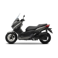
| Model | MBK X-MAX 300 2017 |
| Category | Motorcycle |
| Language | English |