Do you have a question about the Yamaha MC2404 and is the answer not in the manual?
PAD, GAIN, PEAK LED, HIGH, MID, LOW EQ controls adjust sensitivity and tone.
FB 1/2 and ECHO 1/2 controls manage signals sent to foldback and echo busses.
PAN, CUE, CH ON, and Channel Fader controls manage signal assignment and level.
Echo PAN, ECHO RETURN control, and CUE button manage echo return signals and monitoring.
GROUP OUT control and GROUP PAN control manage group signal levels and stereo buss assignment.
GROUP ON button and GROUP Master Fader control group output activation and overall level.
FB and ECHO master controls manage levels for foldback and echo outputs.
STEREO ON button and STEREO L master fader control stereo output activation and level.
PHONES jack, CUE/PHONES LEVEL control, and CUE buttons for headphone monitoring.
Talkback Assign Switches, INPUT connector, and TALKBACK switch for communication.
Channel inputs, insert points, and sub-ins for expanded connectivity.
Voltage selector and phantom power switch for setup and microphone support.
ECHO RETURN, ECHO SEND, GROUP OUT, FB OUT, and STEREO OUT connectors for signal routing.
POWER switch and AC POWER CORD for connecting and operating the unit.
Procedures for safe AC power connection and grounding to prevent noise and hazards.
Guidance on using balanced/unbalanced cables and avoiding ground loops for optimal signal integrity.
How to match input sensitivity using pad switch and gain control for various sources.
Utilizing Low, Mid, and High EQ controls for effective tone shaping and feedback control.
Diagram and explanation of a typical sound reinforcement setup using the mixer.
Diagram and explanation of a recording studio setup utilizing the mixer's routing capabilities.
Diagram and explanation for a theatrical application with stage mics and effects.
Frequency response, THD, noise level, crosstalk, and peak indicator details.
Power requirements, consumption, physical dimensions, and unit weight.
Details on input terminals, impedance, source impedance, and sensitivity levels.
Details on output terminals, impedance, load impedance, and output levels.
A visual representation of the mixer's internal signal paths and connections.
A more detailed block diagram illustrating signal processing stages.
A diagram illustrating signal levels and headroom across various stages of the mixer.
How to install and use a ground lift switch for portable system grounding.
Recommended cable types and wiring for connecting various remote devices.
Balanced XLR, 8 busses, insert points, 3-band EQ, and phantom power for flexibility.
On/Off switches, talkback system, pan/group assignment, and rugged build for ease of use.
Frequency response, THD, noise levels, and crosstalk characteristics.
Detailed tables for input/output terminals, impedance, sensitivity, and levels.
| Brand | Yamaha |
|---|---|
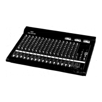
| Model | MC2404 |
| Category | Music Mixer |
| Language | English |