Do you have a question about the Yamaha mc-1202 and is the answer not in the manual?
Guidelines for safe operation concerning environment, physical handling, and cable management.
Covers unit maintenance, power connection safety, cleaning, and correct power source usage.
Attenuates input signal by 20 dB to handle high-level signals and prevent overloading.
Adjusts input sensitivity from -60 dB to -20 dB for optimal signal matching.
Indicates when the post-EQ signal is 3 dB below clipping level.
Features shelving LOW/HIGH and peaking MID controls with sweepable MID FREQ.
Control levels sent to three independent AUX busses for external effects or power amps.
Determine the position of the sound in the stereo field, from far left to far right.
Feeds the pre-EQ/pre-fader signal to the PHONES output for monitoring.
Main level control for each input channel, determining signal sent to the master stereo buss.
Adjust overall output levels for AUX mixes and allows sending AUX signal to PHONES.
Adjust the level of returned signals from effect units into the main stereo program.
Controls for talkback microphone activation, level adjustment, and bus assignment.
Feature three VU meters for monitoring signal levels, with assignable AUX/CUE meter.
Adjusts cue signal level for headphones; accepts standard stereo headphones.
Sends main stereo program buss signal to the stereo PHONES jack for monitoring.
Controls for powering the unit ON/OFF and applying phantom power to LO-Z inputs.
Various input connectors including HI-Z, LO-Z, and insert jacks for signal routing.
Jacks for sending signals to external effects/amps and returning signals from them.
Connectors for cascading units and providing main stereo program outputs.
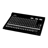
| Brand | Yamaha |
|---|---|
| Model | mc-1202 |
| Category | Music Mixer |
| Language | English |