II-6
5. Motor-Driven Type (Shank stop: 4.5–6.5 mm; Let-off: 5.5–8.5 mm)
●
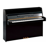
Adjust the shank stopper’s rest position.
Where to adjust: Drive arm stroke adjustment screw. (Locked with a 7 mm nut.) (Fig. 1)
(Located at the bass end of the hammer shank stopper unit.)
Adjustment range: With the hammer pushed against the string, adjust so that the gap between the
shank and its stopper is 2 to 4 mm. (Fig. 2)
●
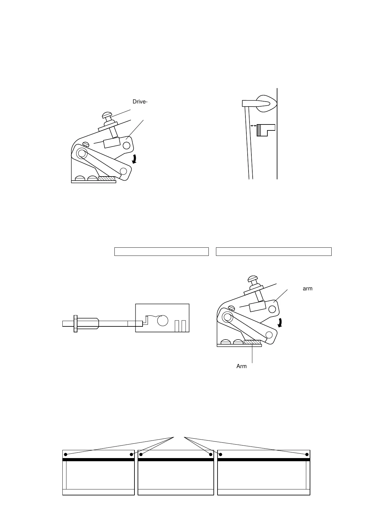
Adjust the shank stopper’s stroke end.
Where to adjust: Cable stroke adjuster (Fig. 3)
How to adjust: Enter silent mode. Rotate the cable stroke adjuster so that the drive arm is just in
contact with the arm cushion.
How to confirm: (When silent mode is switched ON, the following should occur simultaneously.
=
In most cases, this adjustment causes the hammer shank to stop 4.5 to 6.5 mm from the strings.
• If after completing the above adjustments you also need to adjust one or more of the sections sepa-
rately, loosen the relevant (H) screws and adjust the rail position forward or back.
Where to adjust: Stopper position adjustment screws (H).
(There are two screws on each section, one at each end.)
Adjustment range: Adjust to eliminate unevenness among sections, taking care to keep the hammer
shank stopper at a distance of 4.5 to 6.5 mm from the strings.
Drive-arm-stroke
adjustment screw
Drive arm
2 ~ 4 mm
String
<Fig. 1> <Fig. 2>
MD sheet green LED goes OFF The drive arm contacts the arm cushion
Cable stroke adjuster
10 mm
hexagon
8 mm
hexagon
MD unit
LED
RedGreen
Drive arm
Arm cushion
<Fig. 3>
(H)
 Loading...