Do you have a question about the Yamaha SVC210 and is the answer not in the manual?
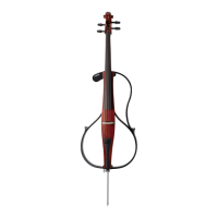
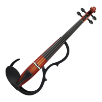
Details the front components of the cello.
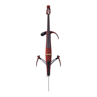
Identifies components on the rear of the cello.
Describes the controls and connections on the unit's panel.
Shows component placement on the rear circuit board.
Detailed diagram of the MA circuit board layout.
Detailed diagrams for HP and JK circuit boards.
Pre-disassembly tasks and removal of initial components.
Steps to remove the control panel and MA circuit board.
Procedures for removing JK and HP circuit boards.
Steps for removing pickup assembly and separating body/neck.
Detailed pin functions for Large Scale Integration (LSI) chips.
Schematic block diagrams of key integrated circuits.
Complete schematic of the cello's electronic circuit.
Initial unit settings and required instruments for inspections.
Procedures for electrical output and reverb time inspections.
Checks and adjustments for mechanical noises and operational issues.
| Size | 4/4 |
|---|---|
| Body Material | Spruce |
| Side Material | Maple |
| Neck Material | Maple |
| Fingerboard Material | Ebony |
| Tuning Pegs | Ebony |
| Bridge | Maple |
| Strings | D'Addario Helicore |
| Sensor | Piezo Pickup |
| Input/Output | Line Out, Headphone Out, AUX In |
| Bow | Not included |
| Color | Brown |
| Tailpiece | Wittner Ultra |
| Controls | Volume |
| Output | Headphones |
| Accessories | Headphones, Cable |